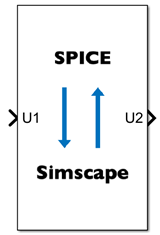
SIMetrix Cosimulation Interface
Libraries:
Simscape /
Electrical /
Additional Components /
Cosimulation
Description
The SIMetrix Cosimulation Interface block creates a virtual connection between Simulink® signals and Simscape™ Electrical™ nodes and a SIMetrix netlist. Use this block to run cosimulations using Simscape and SIMetrix. By running cosimulations, you can incorporate designs developed in different tools into a Simscape model. For example, you can:
Model electronics in SIMetrix using models provided by device manufacturers.
Design electrical, electromechanical, and other multidomain systems using Simscape.
Design control systems using Simulink.
Cosimulation can improve team integration. You can build a system-level model that models semiconductor devices with ideal switching using Simulink and Simscape. Then, to validate the model, you can run a cosimulation using detailed designs of the electronics developed in SIMetrix. You can also use cosimulation to test circuits developed in SIMetrix against a realistic load, such as a motor in Simscape Electrical.
Cosimulation is an alternative to the subcircuit2ssc
function, which converts SPICE subcircuits to an equivalent Simscape component. Cosimulation
is usually the better choice for SPICE models developed in SIMetrix. The
subcircuit2ssc function is useful only to convert circuits with a small
number of R, L, C, and transistor devices. Large networks of semiconductor devices are more
challenging to simulate and only simulate reliably by using the SPICE simulation engine for
which they were originally written.
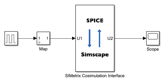
To run cosimulations, you also need to use a Cosimulation Interface in your SIMetrix schematic. This figure shows how the Cosimulation Interface in SIMetrix exchanges information with the SIMetrix Cosimulation Interface block in Simscape.
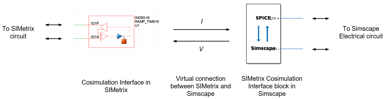
In your Simscape model, the SIMetrix Cosimulation Interface block represents the part of your electrical network that you want to simulate in SIMetrix. You can connect this block to a Simulink block diagram by using signal lines or to an electrical network in Simscape by using physical connection lines. You can also choose whether SIMetrix sends voltage or current values to Simscape.
You can build your SIMetrix schematic and Simscape model independently. However, the number, name, and type of the ports of the SIMetrix Cosimulation Interface block depend on the options you select for the Cosimulation Interface in SIMetrix. To prepare the models for cosimulation, you therefore need to update the SIMetrix schematic first. To use the SIMetrix Cosimulation Interface block in your Simscape model, you first need to save your SIMetrix schematic, with a predefined interface with Simulink, as a netlist:
Build a schematic of the electronics that you want to simulate in SIMetrix.
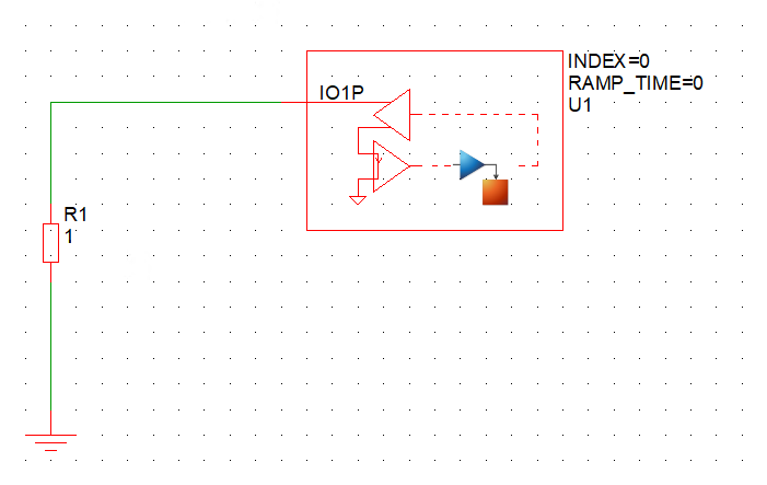
Create a Cosimulation Interface in the SIMetrix schematic — In the Command Shell, enter
Simulink_create_interface_symbol.Configure the Cosimulation Interface and connect it to your circuit — How you do this depends on what information you want SIMetrix and Simscape to exchange. For more information about completing this step, see Create Virtual Connections.
Convert the schematic into a netlist — In the SIMetrix Command Shell, enter
netlistfollowed by the name of your netlist. For example,netlist yourNetlistName.net.
After you save your netlist in SIMetrix, you build the block diagram or electrical network that you want to simulate in Simscape. You then use the SIMetrix Cosimulation Interface block to create virtual connections between your SIMetrix and Simscape models. Specify the file path of the SPICE netlist using the Netlist file path parameter of the SIMetrix Cosimulation Interface block or click the Browse button to select the SPICE netlist using your system browser. Then, to build the input/output device, click the Build I/O button. This action creates the virtual connections between SIMetrix and Simscape and enables the correct ports in the SIMetrix Cosimulation Interface block.
You set the fixed rate at which SIMetrix provides output to Simulink, using the Sample time (s) parameter. In between sample times, SIMetrix runs with a variable step solver. You must set the Sample time (s) parameter to a value that it small enough for Simulink to capture the important dynamics from the SIMetrix simulation. This configuration, with a variable time step for the SIMetrix simulation sampled at a fixed rate in the Simulink simulation, means that cosimulation works most efficiently when you model the faster dynamics in SIMetrix and model the slower dynamics in Simulink or Simscape. For example, cosimulation works efficiently when you model a motor drive by modeling the power electronics in SIMetrix and modeling the motor and mechanical load in Simscape.
When you run the model, SIMetrix and Simscape simulate together. SIMetrix and Simscape can both store the results. You can visualize and postprocess the data using either software.
The SIMetrix Cosimulation Interface block supports SIMetrix Pro and SIMetrix Elite 9.1 and beyond.
Create Virtual Connections
The number, name, and type of the ports of the SIMetrix Cosimulation Interface block depend on the options you select for the Cosimulation Interface in SIMetrix. To create virtual connections, you need to understand these options.
The Configuration parameter determines whether SIMetrix sends information to or receives information from Simulink or Simscape. The Input connections and Output connections parameters determine the nature of this information. You can exchange values of current, voltage, or both. You can also choose whether to measure voltage values relative to ground or to model two separate connections. The Number of ports parameter determines the number of ports of the Cosimulation Interface in SIMetrix.
You can set the Configuration parameter to:
Input only— SIMetrix sends voltage or current values as input to Simulink. Selecting this option enables the Input connections parameter. The corresponding SIMetrix Cosimulation Interface block has a Simulink output port.Output only— SIMetrix receives voltage or current values as output from Simulink. Selecting this option enables the Output connections parameter. The corresponding SIMetrix Cosimulation Interface block has a Simulink input port.Combined Input Output V/I or I/V— SIMetrix sends voltage or current values to Simscape and receives current or voltage values from Simscape. Selecting this option enables the Output connections parameter. SIMetrix automatically selects the appropriate value for the Input connections parameter. The corresponding SIMetrix Cosimulation Interface block has one or two Simscape conserving ports.
You can set the Input connections or Output connections parameter to:
Single-ended VoltageDifferential VoltageSingle-ended CurrentDifferential Current
Choosing Single-ended Voltage or Single-ended
Current effectively grounds and hides the negative terminals.
If you set the Configuration parameter to Combined
Input Output V/I or I/V, the input and output configuration must have the
same number of ports and have the same type of connection, either single-ended or
differential. If you also set the Output Connections parameter to
Single-ended Voltage or Single-ended
Current, the SIMetrix Cosimulation Interface block has one conserving port. If you set the
Output Connections parameter to Differential
Voltage or Differential Current, the SIMetrix Cosimulation Interface
block has two conserving ports.
This table summarizes how SIMetrix exchanges information with Simulink or Simscape. The table also shows the types of ports that the corresponding SIMetrix Cosimulation Interface has and the names of those ports.
| Configuration Parameter Value | Input Connections Parameter Value | Output Connections Parameter Value | Information Exchange | SIMetrix Cosimulation Interface Block Port Type | SIMetrix Cosimulation Interface Simulink Block Diagram |
|---|---|---|---|---|---|
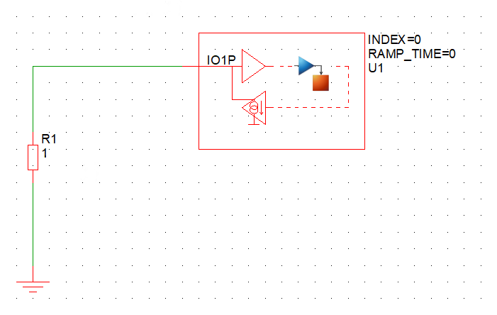
Input Only | Single-ended Voltage | N/A | SIMetrix sends voltage values as input to Simulink. | Simulink output port U1 |
|
Differential Voltage | N/A | ||||
Single-ended Current | N/A | SIMetrix sends current values as input to Simulink. | |||
Differential Current | N/A | ||||
Output Only | N/A | Single-ended Voltage | SIMetrix receives voltage values as output from Simulink. | Simulink input port U1 |
|
| N/A | Differential Voltage | ||||
| N/A | Single-ended Current | SIMetrix receives current values as output from Simulink. | |||
| N/A | Differential Current | ||||
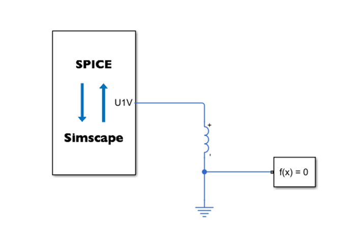
Combined Input Output V/I or
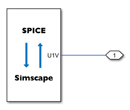
I/V | Single-ended Current | Single-ended Voltage | SIMetrix sends current values to Simscape and receives voltage values from Simscape. | Simscape conserving port U1V |
|
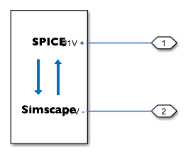
Differential Current | Differential Voltage | Simscape conserving ports U1V+ and U1V- |
| ||
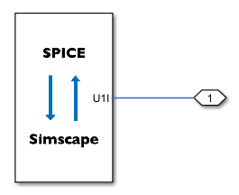
Single-ended Voltage | Single-ended Current | SIMetrix sends voltage values to Simscape and receives current values from Simscape. | Simscape conserving port U1I |
| |
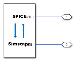
Differential Voltage | Differential Current | Simscape conserving ports U1I+ and U1I- |
|
Note
The number, name, and type of the ports in this table always apply if you have a
single Cosimulation Interface in SIMetrix. However, one SIMetrix Cosimulation Interface block corresponds to
one SIMetrix schematic or netlist, not one Cosimulation Interface. You can build a
SIMetrix Cosimulation Interface block with more ports and multiple port types by using multiple Cosimulation
Interfaces in SIMetrix. SIMetrix labels each Cosimulation Interface Uk,
where k is an integer between 1 and the number of
Cosimulation Interfaces in the schematic. These numbers correspond to the numbers in the
port names of the SIMetrix Cosimulation Interface block.
The Number of ports parameter defines the number of ports of the
Cosimulation Interface in SIMetrix. This parameter does not affect the number of ports of
the SIMetrix Cosimulation Interface block in Simscape. Instead, the port type changes to support the correct
number of voltage or current values. If you set this parameter to 1:
Simulink input and output ports carry scalar signals.
Simscape ports are electrical conserving ports.
If you set this parameter to a value greater than 1:
Simulink input and output ports carry vector signals.
Simscape ports are electrical array-of-nodes conserving ports. You can connect the SIMetrix Cosimulation Interface block to your electrical network by using an Array Connection block.
To create connections between a SIMetrix schematic and a Simscape Electrical network,
set the Configuration parameter of the Cosimulation Interface in
SIMetrix to Combined Input Output V/I or I/V.
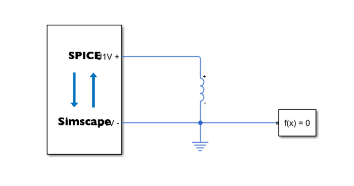
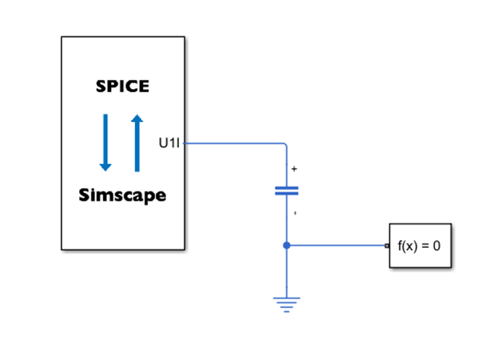
To model an inductive load or current source in Simscape, set the Output
connections parameter to Single-ended Voltage or
Differential Voltage. To model a capacitive load or voltage
source in Simscape, set the Output connections parameter to
Single-ended Current or Differential
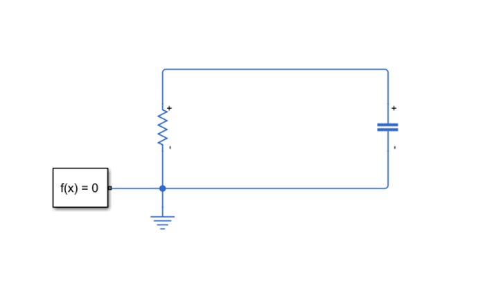
Current. To model a purely resistive load in Simscape, you can use any of
these options.
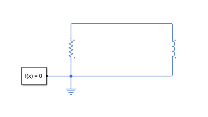
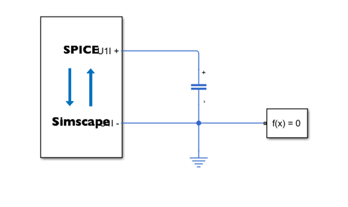
This table shows simple examples of corresponding SIMetrix schematics and Simscape networks for cosimulation. The table also shows the equivalent electrical network modeled entirely in Simscape. The Inductor and Capacitor blocks in the Simscape networks represent any inductive or capacitive load, respectively.
| Goal | Input Connections | Output Connections | Example SIMetrix Schematic for Cosimulation | Example Simscape Network for Cosimulation | Equivalent Simscape Network |
|---|---|---|---|---|---|
| Model an inductive load in Simscape | Single-ended Current | Single-ended Voltage |
|
|
|
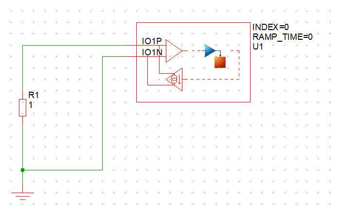
Differential Current | Differential Voltage |
|
| ||
| Model a capacitive load in Simscape | Single-ended Voltage | Single-ended Current |
|
|
|
Differential Voltage | Differential Current |
|
|
To create virtual connections between a SIMetrix schematic and a Simulink block
diagram, set the Configuration parameter of the Cosimulation
Interface in SIMetrix to Input only or Output
only. These figures show a simple example with both an input and an
output.
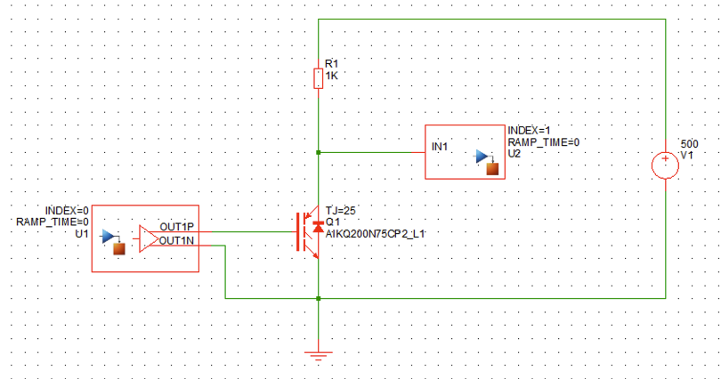
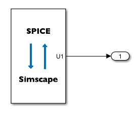
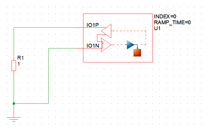
The Simulink input port, U1, sends the gate-emitter voltage signal to the
IGBT in the SIMetrix schematic. This port corresponds to the U1
Cosimulation Interface in SIMetrix. To create the virtual connection, in the Cosimulation
Interface set:
Configuration to
Output onlyOutput connections to
Differential
                  Voltage
Number of ports to
1
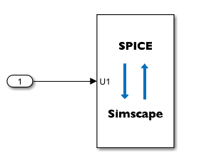
The Simulink output port, U2, receives the single-ended collector voltage
signal from the IGBT in SIMetrix. This port corresponds to the U2
Cosimulation Interface in SIMetrix. To create the virtual connection, in the Cosimulation
Interface set:
Configuration to
Input onlyInput connections to
Single-ended
                Voltage
Number of ports to
1.
Assumptions and Limitations
In SIMetrix, you can set the Configuration parameter of the Cosimulation Interface to:
Input onlyOutput onlySeparate Input OutputCombined Input Output V/I or I/V
The SIMetrix Cosimulation Interface block does not support the
Separate Input Outputoption.You cannot run cosimulations using a Simscape model with more than one SIMetrix Cosimulation Interface block.
The SIMetrix Cosimulation Interface block supports up to 16 ports.
Ports
Note
The SPICE netlist defines the name, type, and number of ports of the SIMetrix Cosimulation Interface block. To update the ports after changing the parameters of the Cosimulation Interface in SIMetrix, convert the schematic into a netlist and build the input/output device in Simscape. For more information, see the Description section.
Input
Output
Conserving
Parameters
Version History
Introduced in R2025a
See Also
Functions
subcircuit2ssc|ee.spice.semiconductorSubcircuit2lookup|ee.spice.diodeSubcircuit2lookup|generateSemiconductorSubcircuitROM