series
Series connection of two models
Description
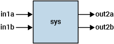
sys = series(sys1,sys2)sys1 to the inputs of sys2, as shown in the
diagram.
This command is equivalent to the direct multiplication sys =
sys2*sys1. For MIMO systems, the number of inputs of sys2
must equal the number of outputs of sys1. The resulting
sys has inputs u and outputs y.
sys = series(sys1,sys2,out1,in2)sys1 to a subset of the inputs of
sys2.
out1 is a vector specifying the indices of the outputs of
sys1 to connect. Similarly, in1 specifies the
indices of the inputs of sys2 to connect to those outputs. The
resulting sys has inputs u and outputs
y. series drops unconnected outputs
z1 of sys1 and unconnected inputs
v2 of sys2.
Examples
Create two SISO systems, one a state-space model and the other a transfer function.
sys1 = rss(3);
sys2 = tf(1,[1 1 1]);
Form the series connection of the two systems.
sys = series(sys1,sys2);
size(sys)
State-space model with 1 outputs, 1 inputs, and 5 states.
Connecting a transfer function with a state-space model results in another state-space model. For more information about the results of combining different model types, see Rules That Determine Model Type.
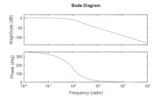
The series interconnection is equivalent to the product sys2*sys1. Check this equivalence by examining the frequency responses.
sysm = sys2*sys1;
bodeplot(sys,'-',sysm,'--')
Connect two MIMO systems in series. When number of outputs of sys1 equals the number of inputs of sys2, you can connect all sys1 outputs to all sys2 inputs.
sys1 = rss(3,2,3);
sys2 = rss(3,3,2);
sys = series(sys1,sys2);
The resulting system has the same number of inputs as sys1 and the same number of outputs as sys2/.
size(sys)
State-space model with 3 outputs, 3 inputs, and 6 states.
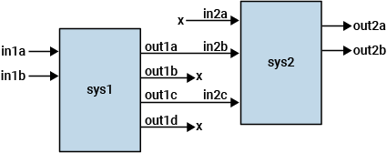
You can form serial connections by assigning matching names to the signals you want to connect. Starting with the four-output, two-input system sys1 and the two-output, three-input system sys2, form the series connection shown in the diagram.
Create state-space models of the two systems and name the input and output signals.
% sys1: 4-output, 2-input
sys1 = rss(4,4,2);
sys1.InputName = ["in1a","in1b"];
sys1.OutputName = ["out1a","out1b","out1c","out1d"];
% sys2: 2-output, 3-input
sys2 = rss(3,2,3);
sys2.InputName = ["in2a","in2b","in2c"];
sys2.OutputName = ["out2a","out2b"];
In the interconnection shown in the diagram, out1a and out1c of sys1 connect to in2b and in2c, respectively. Change the signal names so that the names of connecting signals match.
sys1.OutputName = ["ua","out1b","ub","out1d"];
sys2.InputName = ["in2a","ua","ub"];
Form the connection by calling series with the name flag.
sys = series(sys1,sys2,"name");Examine the dimensions, inputs, and outputs of sys to confirm that the connections match the ones in the diagram.
size(sys)
State-space model with 2 outputs, 2 inputs, and 7 states.
sys.InputName
ans = 2×1 cell
    {'in1a'}
    {'in1b'}
sys.OutputName
ans = 2×1 cell
    {'out2a'}
    {'out2b'}
As expected, the resulting sys has two outputs and two inputs, corresponding to the outputs of sys2 and the inputs of sys1, respectively.
sys drops unconnected inputs of sys2 and unconnected outputs of sys1. To form this interconnection preserving all inputs and outputs, use connect instead, specifying all the inputs and outputs you want to preserve in the resulting system.
sysc = connect(sys1,sys2,["in1a","in1b","in2a"],["out2a","out2b","out1b","out1d"]);
size(sysc)
State-space model with 4 outputs, 3 inputs, and 7 states.
sysc.InputName
ans = 3×1 cell
    {'in1a'}
    {'in1b'}
    {'in2a'}
sysc.OutputName
ans = 4×1 cell
    {'out2a'}
    {'out2b'}
    {'out1b'}
    {'out1d'}
You can form series interconnections using a subset of model inputs and outputs by specifying the indices of the signals you want to connect. Starting with the four-output, two-input system sys1 and the two-output, three-input system sys2, form the series connection shown in the diagram.

Create state-space models of the two systems.
% sys1: 4-output, 2-input
sys1 = rss(4,4,2);
% sys2: 2-output, 3-input
sys2 = rss(3,2,3);
To form the series connection, create vectors that specify the outputs of sys1 and the corresponding inputs of sys2 to connect. In the diagram, the first and third outputs of sys1 connect to the second and third inputs of sys2, respectively. Therefore, specify the indices as follows.
out1 = [1 3]; % out1a and out1c
in2 = [2 3];  % in2b and in2c
Form the connection and examine the size of the output.
sys = series(sys1,sys2,out1,in2);
size(sys)
State-space model with 2 outputs, 2 inputs, and 7 states.
As expected, the resulting sys has two outputs and two inputs, corresponding to the outputs of sys2 and the inputs of sys1, respectively. sys drops unconnected inputs of sys2 and unconnected outputs of sys1. To form this interconnection preserving all inputs and outputs, use connect.
Input Arguments
Output Arguments
Version History
Introduced before R2006a