Create and Manage Allocations Interactively
This example shows how to create and manage System Composer™ allocations interactively on the model canvas and using the Allocation Editor.
In systems engineering, an architectural system is commonly described on different levels. Functional architectures [1] describe the high-level functions of a system. Logical architectures [2] describe the logical components of a system and how data is exchanged between them. You can use allocations to establish relationships from functional components to logical components and to indicate deployment strategies.
An allocation establishes a directed relationship from architectural elements — components, ports, and connectors — in one model to architectural elements in another model. Resource-based allocation allows you to allocate functional architectural elements to logical architectural elements and logical architectural elements to physical architectural elements.
An allocation scenario contains a set of allocations between a source and a target model. Allocate between model elements in an allocation scenario. The default allocation scenario is called
Scenario 1.An allocation set consists of one or more allocation scenarios that describe various allocations between a source and a target model. Create an allocation set with allocation scenarios in the Allocation Editor. Allocation sets are saved as MLDATX files.
To create allocations programmatically, see Create and Manage Allocations Programmatically.
Tip
To learn more about how System Composer concepts apply to systems engineering design, see System Composer Concepts.
Create and Manage Allocations Interactively Using Tire Pressure Monitoring System
This example uses the Tire Pressure Monitoring System (TPMS) project. To open the project, use this command.
openProject("scExampleTirePressureMonitorSystem");Create Allocations Between Two Models
You can create allocations between a functional architecture and a logical architecture of the TPMS to represent directed relationships between components, ports, and connectors.
1. Open the functional architecture model, which is the source model for allocations.
systemcomposer.openModel("TPMS_FunctionalArchitecture");2. To create an allocation set for these models, launch the Allocation Editor by navigating to Modeling > Allocation Editor from the toolstrip.
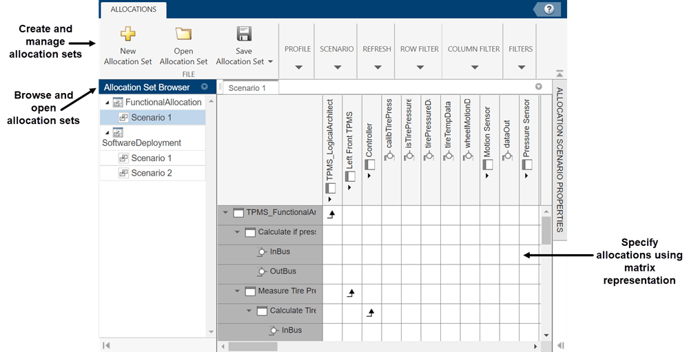
The Allocation Editor has three parts: the toolstrip, the browser pane, and the allocation matrix.
Use the toolstrip to create and manage allocation sets.
Use the Allocation Set Browser pane to browse and open existing allocation sets.
Use the allocation matrix to specify allocations between the source model elements in the first column and target model elements in the first row. You can create allocations programmatically or by double-clicking a cell in the matrix.
3. Click New Allocation Set to create a new allocation set between two models and set the name. In this example, TPMS_FunctionalArchitecture.slx is the source model, and TPMS_LogicalArchitecture.slx is the target model.

4. To create an allocation between two elements of the same type from the source model to the target model, double-click the corresponding cell in the allocation matrix. Double-click the cell for the Report Low Tire Pressure component on the source model and the TPMS Reporting System component on the target model.

5. To show allocations on model elements for the source model TPMS_FunctionalArchitecture, on the toolstrip, navigate to Modeling > Allocation Editor > Show Allocations. Select the Report Low Tire Pressure source component and click the allocated to symbol. You will see the full path of the target component.
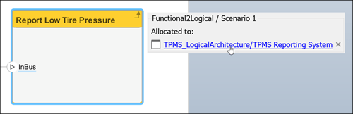
6. Click the target component to navigate to it on the target model.
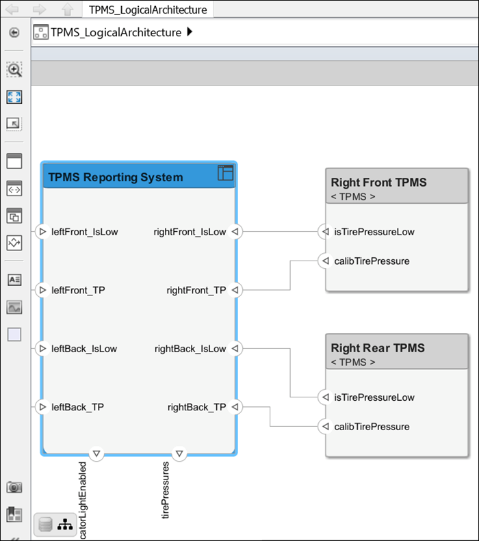
7. Return to the source model TPMS_FunctionalArchitecture and create a new allocation from a model element. Right-click the Calculate if pressure is low component, and from the tooltip select Allocations, then select Select as allocation source.
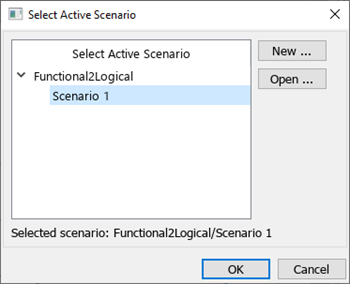
8. On the target model TPMS_LogicalArchitecture, right-click the TPMS Reporting System component, from the tooltip, select Allocations. Then, select Allocate to selected element. Choose the active allocation scenario.
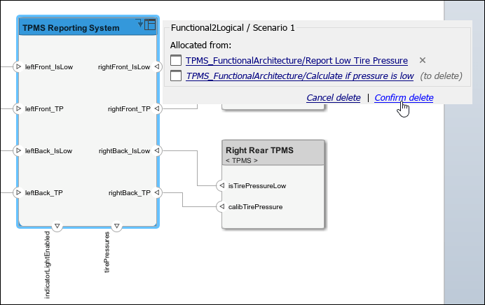
9. To show allocations on model elements for the target model TPMS_LogicalArchitecture, on the toolstrip, navigate to Modeling > Allocation Editor > Show Allocations. Click the allocated from symbol on the TPMS Reporting System component to view the full path of the two allocated-from components. Click the ![]() icon on either component to delete the allocation and deallocate the components. Click
icon on either component to delete the allocation and deallocate the components. Click Confirm delete to continue deleting.
Assign Stereotypes to Allocations
Stereotypes on allocations capture metadata on the relationship between model elements to map from one environment to another.
1. Open the Profile Editor from the Allocation Editor. Create a stereotype called FunctionalAllocation in your profile that applies to allocations. Then, define a property called IsImplemented of type boolean.

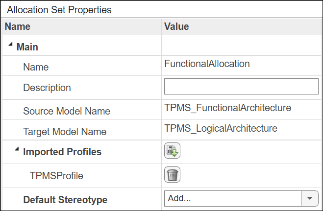
2. Return to the Allocation Editor and select the FunctionalAllocation allocation set. Import the TPMSProfile profile on the Allocation Set Properties tab by clicking the ![]() button.
button.
3. Click Scenario 1 on the FunctionalAllocation allocation set. Select an allocation. From the Allocation Properties tab, select the FunctionalAllocation stereotype.

You can now check the IsImplemented property to indicate that the functional to logical allocation is implemented. Properties represent a directed relationship from a source model to a target model and extend the architectural modeling language.
References
[1] Carter, Jeffrey. “Functional Architecture.” Guide to the Systems Engineering Body of Knowledge (SEBoK) v. 2.7, released October 31, 2022. https://sebokwiki.org/wiki/Functional_Architecture.
[2] Faisandier, Alan, Garry Roedler, and Rick Adcock. “Logical Architecture.” Guide to the Systems Engineering Body of Knowledge (SEBoK) v. 2.7, released October 31, 2022. https://sebokwiki.org/wiki/Logical_Architecture.
See Also
Objects
systemcomposer.allocation.AllocationScenario|systemcomposer.allocation.AllocationSet|systemcomposer.allocation.Allocation