FIR Rate Conversion
Perform polyphase FIR sample rate conversion
Libraries:
DSP System Toolbox /
Filtering /
Multirate Filters
Description
The FIR Rate Conversion block performs an efficient polyphase sample rate conversion using a rational factor L/M along the first dimension. The block treats each column of the input as a separate channel and resamples the data in each channel independently over time.
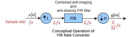
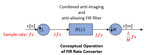
Conceptually, the rate converter combines an FIR interpolator followed by an FIR decimator.
The following schematic contains an upsampler, a combined anti-imaging and anti-aliasing
FIR filter, and a downsampler. To design an FIR filter which acts as a combined
anti-imaging and anti-aliasing FIR filter, use the designMultirateFIR function.
The rate converter does the following:
Upsamples the input to a higher rate by inserting L−
1zeros between input samples.Passes the upsampled data through an FIR filter.
Downsamples the filtered data to a lower rate by discarding M-
1consecutive samples following each sample that the block retains.
Note that the actual block algorithm implements a polyphase structure, an efficient equivalent of the combined system depicted in the diagram. For more details, see Algorithms.
Examples

GSM Digital Down Converter in Simulink
Simulate steady-state behavior of a fixed-point digital down converter for GSM (Global System for Mobile) baseband conversions. The example model uses blocks from Simulink® and the DSP System Toolbox™ to emulate the operation of the TI GC4016 Quad Digital Down Converter (DDC).
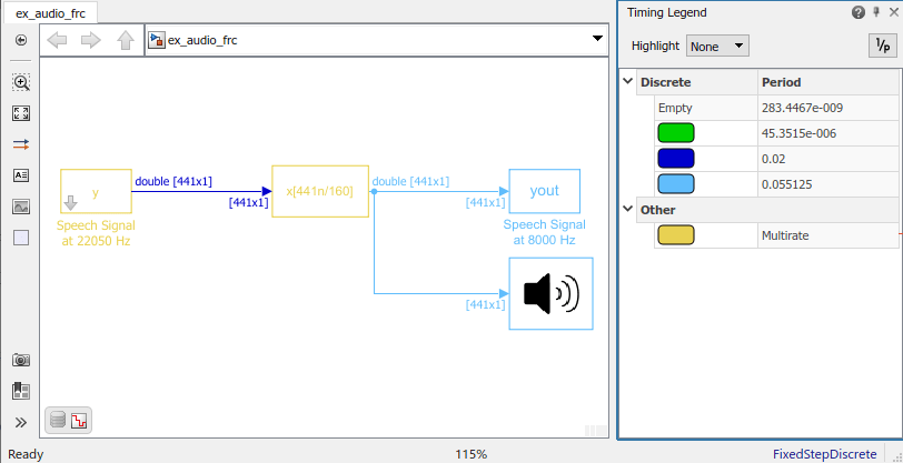
Convert Sample Rate of Speech Signal
Convert sample rate of speech signal.
Ports
Input
Output
Parameters
The FIR Rate Conversion block can operate in three different modes. Select the mode in the Coefficient source group box.
Dialog parameters — Enter information about the filter, such as FIR filter coefficients in the block dialog box.
Filter object — Specify the filter using a
dsp.FIRRateConverterSystem object™.Auto (default) — The block determines the filter coefficients.
The settings in the FIR Rate Conversion block dialog box change based on the mode selected.
Main Tab
Specify the interpolation factor, L, as a positive integer. The block upsamples the signal by this value before filtering it.
Dependencies
To enable this parameter, set Coefficient source to either Dialog parameters or Auto.
Data Types: single | double | int8 | int16 | int32 | int64 | uint8 | uint16 | uint32 | uint64
Specify the FIR filter coefficients in descending powers of
z. By default, the block uses the
designMultirateFIR(3,2) function to compute the
filter coefficients.
Dependencies
To enable this parameter, set Coefficient source to Dialog parameters.
Data Types: single | double | int8 | int16 | int32 | int64 | uint8 | uint16 | uint32 | uint64
Complex Number Support: Yes
Specify the decimation factor, M, as a positive integer. The block downsamples the signal by this value after filtering it.
Dependencies
To enable this parameter, set Coefficient source to either Dialog parameters or Auto.
Data Types: single | double | int8 | int16 | int32 | int64 | uint8 | uint16 | uint32 | uint64
Specify whether to enforce single-rate processing or allow multirate processing.
Enforce single-rate processing— The output frame size Po is L/M times the input frame size Pi, where L is the interpolation factor and M is the decimation factor.Po = (L/M)×Pi
The output signal rate in Simulink® equals the input signal rate.
Fo = Fi
Allow multirate processing— The output frame size equals the input frame size.Po = Pi
The output signal rate in Simulink is L/M times the input signal rate.
Fo = (L/M)×Fi
All blocks connected to the output operate at Fo, and all blocks connected to the input operate at Fi.
Specify the multirate filter object that you want the block to
implement. The specified filter object must be a dsp.FIRRateConverter
System object.
You can define the System object in the block mask or in a MATLAB® workspace variable.
For information on creating System objects, see Define Basic System Objects.
Dependencies
This parameter appears when Coefficient source is set to Filter object.
Specify whether fixed-size input signals (whose size does not change during simulation) can have an arbitrary frame length, where the frame length does not have to be a multiple of the decimation factor. The block uses this parameter setting only for fixed-size input signals and ignores this parameter if the input has a variable-size.
When the input signal is a variable-size signal, the signal can have arbitrary frame length, that is, the frame length does not have to be a multiple of the decimation factor.
For fixed-size input signals, if you:
Select the Allow arbitrary frame length for fixed-size input signals parameter, the frame length of the signal does not have to be a multiple of the decimation factor. If the input is not a multiple of the decimation factor, then the output is generally a variable-size signal. Therefore, to support arbitrary input size, the block must also support variable-size operations, which you can enable by selecting the Allow arbitrary frame length for fixed-size input signals parameter.
Clear the Allow arbitrary frame length for fixed-size input signals parameter, the input frame length must be a multiple of the decimation factor.
Dependency
To enable this parameter, set Rate options to
Enforce single-rate
								processing
.
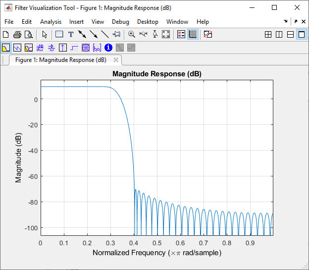
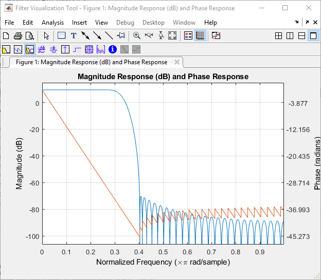
Select this parameter to open the Filter Visualization Tool, fvtool, and display the magnitude response of the FIR
filter. The response is based on the parameters selected in the block
dialog box. Changes made to these parameters update
fvtool.
To update the magnitude response while fvtool is
running, modify the block parameters and click
Apply.
To view the magnitude response and phase response simultaneously, click the Magnitude and Phase responses button on the toolbar.
Data Types Tab
When Coefficient source is set to Filter object, the fixed-point settings of the filter object specified on the Main tab are displayed on the Data Types tab. You cannot change these settings directly on the block dialog box. To change the fixed-point settings, you must edit the filter object.
For more information on System objects, see the What Are System Objects?.
When Coefficient source is set to Auto, the block chooses the filter coefficients automatically. For more information on the filter design algorithm that the block uses, see Specify FIR Filter Coefficients.
Specify the rounding mode for fixed-point operations as:
FloorCeilingConvergentNearestRoundSimplestZero
For more details, see Rounding Modes.
The filter coefficients do not obey this parameter and always round to
Nearest.
Note
The Rounding mode and Saturate on integer overflow parameters have no effect on numerical results when all these conditions are met:
Product output data type is
Inherit: Inherit via internal rule.Accumulator data type is
Inherit: Inherit via internal rule.Output data type is
Inherit: Same as
												accumulator
.
With these data-type settings, the block operates in a full-precision mode.
Dependencies
To enable this parameter, set Coefficient source to either Dialog parameters or Auto.
Select this parameter to saturate the result of the fixed-point operation. Clear this parameter to wrap the result of the fixed-point operation. For details on saturate and wrap, see Overflow Handling for fixed-point operations.
Note
The Rounding mode and Saturate on integer overflow parameters have no effect on numeric results when all these conditions are met:
Product output data type is
Inherit: Inherit via internal rule.Accumulator data type is
Inherit: Inherit via internal
												rule
.
With these data-type settings, the block operates in a full-precision mode.
Dependencies
This parameter is editable only when Coefficient source is set to either Dialog parameters or Auto.
Coefficients specifies the data type of the filter coefficients.
Inherit: Same word length as input— The block inherits the word length of the coefficients from the fixed-point input. The fraction length is determined based on the coefficient values in order to obtain the best possible precision.fixdt(1,16)— The coefficients data type is a signed, binary-point, scaled, fixed-point data type with a word length of 16 bits.fixdt(1,16,0)— The coefficients data type is a signed, binary-point, scaled, fixed-point data type with a word length of 16 bits and a fraction length of 0.
Alternatively, you can set the Coefficients data
type by using the Data Type Assistant. To use the
assistant, click the Show data type assistant
button ![]() .
.
For more information on the data type assistant, see Specify Data Types Using Data Type Assistant (Simulink).
For a diagrammatic representation of how this block uses the filter coefficients data type, see Fixed-Point Data Types.
Dependencies
This parameter is editable only when Coefficient source is set to either Dialog parameters or Auto.
Specify the minimum value of the filter coefficients. Simulink uses this minimum value to perform automatic scaling of fixed-point data types.
Specify the maximum value of the filter coefficients. Simulink uses this maximum value to perform automatic scaling of fixed-point data types.
Product output specifies the data type of the output of a product operation in the FIR Rate Conversion block.
Inherit: Inherit via internal rule— The block inherits the product output data type based on an internal rule. For more information on this rule, see Inherit via Internal Rule.Inherit: Same as input— The block specifies the product output data type to be the same as the input data type.fixdt(1,16,0)— The block specifies a signed, binary-point, scaled, fixed-point data type with a word length of 16 bits and a fraction length of 0.
Alternatively, you can set the Product output
data type by using the Data Type Assistant. To use
the assistant, click the Show data type assistant
button ![]() .
.
For more information on the data type assistant, see Specify Data Types Using Data Type Assistant (Simulink).
For a diagrammatic representation of how this block uses the product output data type, see Fixed-Point Data Types.
Dependencies
This parameter is editable only when Coefficient source is set to either Dialog parameters or Auto.
Accumulator specifies the data type of the output of an accumulation operation in the FIR Rate Conversion block. For illustrations on how this block uses the accumulator data type, see Fixed-Point Data Types.
Inherit: Inherit via internal rule— The block inherits the accumulator data type based on an internal rule. For more information on this rule, see Inherit via Internal Rule.Inherit: Same as input— The block specifies the accumulator data type to be the same as the input data type.Inherit: Same as product output— The block specifies the accumulator data type to be the same as the product output data type.fixdt(1,16,0)— The block specifies a signed, binary-point, scaled, fixed-point data type with a word length of 16 bits and a fraction length of 0.
Alternatively, you can set the Accumulator data
type by using the Data Type Assistant. To use the
assistant, click the Show data type assistant button![]() .
.
For more information on the data type assistant, see Specify Data Types Using Data Type Assistant (Simulink).
Dependencies
This parameter is editable only when Coefficient source is set to either Dialog parameters or Auto.
Output specifies the data type of the output of the FIR Rate Conversion block.
Inherit: Same as input— The block specifies the output data type to be the same as the input data type.Inherit: Same as product output— The block specifies the output data type to be the same as the product output data type.Inherit: Same as accumulator— The block specifies the output data type to be the same as the accumulator data type.fixdt(1,16,0)— The block specifies a signed, binary-point, scaled, fixed-point data type with a word length of 16 bits and a fraction length of 0.
Alternatively, you can set the Output data type
by using the Data Type Assistant. To use the
assistant, click the Show data type assistant
button ![]() .
.
For more information on the data type assistant, see Specify Data Types Using Data Type Assistant (Simulink).
For a diagrammatic representation of how this block uses the output data type, see Fixed-Point Data Types.
Dependencies
This parameter is editable only when Coefficient source is set to either Dialog parameters or Auto.
Specify the minimum value the block can output. Simulink uses this minimum value to perform:
Simulation range checking. For more information, see Specify Signal Ranges (Simulink).
Automatic scaling of fixed-point data types.
Specify the maximum value the block can output. Simulink uses this maximum value to perform:
Simulation range checking. For more information, see Specify Signal Ranges (Simulink).
Automatic scaling of fixed-point data types.
Select this parameter to prevent the fixed-point tools from overriding the data types you specify on the block dialog box.
Dependencies
This parameter appears only when Coefficient source is set to either Dialog parameters or Auto.
Block Characteristics
Data Types |
|
Direct Feedthrough |
|
Multidimensional Signals |
|
Variable-Size Signals |
|
Zero-Crossing Detection |
|
More About
This section applies only to the single-rate processing mode when the Rate
options parameter is set to Enforce single-rate
processing.
You specify the resampling rate of the FIR Rate Conversion block using the Decimation factor and Interpolation factor parameters. For a Pi-by-Q matrix input, the Decimation factor M and the Interpolation factor L must satisfy these requirements:
M and L must be relatively prime integers. That is, the ratio M/L cannot be reduced to a ratio of smaller integers.
, where Pi and Po are the integer frame sizes of the input and output, respectively.
You can satisfy the second requirement by setting the Decimation factor, M, to equal the input frame size Pi. When you do so, the output frame size Po equals the Interpolation factor L.
By changing the frame size in this way, the block is able to hold the frame period constant (Tfi = Tfo) and achieve the desired conversion of the sample period, such that
where Tso is the output sample period.
This figure shows how the FIR Rate Conversion block converts a
4-by-1 input with a sample period of
3/4 to a
3-by-1 output with a sample period of
1. The frame period
(Tf) of 3
remains constant.

This diagram shows the data types used within the FIR Rate Conversion block for fixed-point signals.
You can set the coefficient, product output, accumulator, and output data types in the block dialog box. The diagram shows that input data is stored in the input buffer in the same data type and scaling as the input. Filtered data resides in the output buffer in the output data type and scaling that you set in the block dialog. The block stores any initial conditions in the output buffer using the output data type and scaling that you set in the block dialog box.
The output of the multiplier is in the product output data type when at least one of the inputs to the multiplier is real. When both the inputs to the multiplier are complex, the result of the multiplication is in the accumulator data type. For details on how the complex multiplication is performed in the block, see Multiplication Data Types.
Note
When the block input is fixed point, all internal data types are signed fixed point.
Algorithms
The FIR rate converter is implemented efficiently using a polyphase structure.
To derive the polyphase structure, start with the transfer function of the FIR filter: This FIR filter is a combined anti-imaging and anti-aliasing filter.
N+1 is the length of the FIR filter.
You can rearrange this equation as follows:
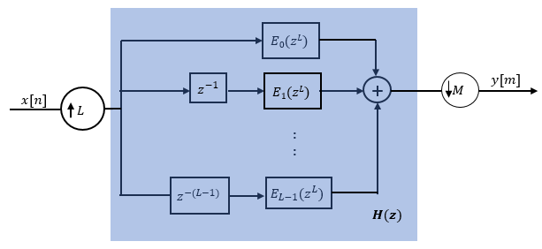
L is the number of polyphase components, and its value equals the interpolation factor that you specify.
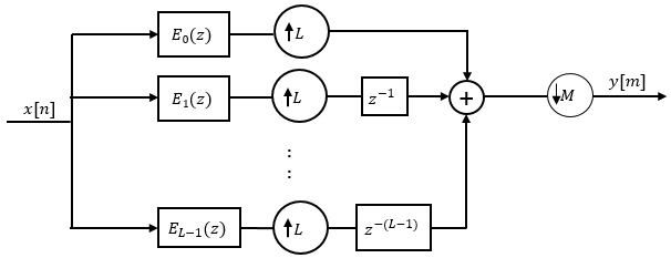
You can write this equation as:
E0(zL), E1(zL), ..., EL-1(zL) are polyphase components of the FIR filter H(z).
Conceptually, the FIR rate converter contains an upsampler, followed by a combined anti-imaging, anti-aliasing FIR filter H(z), which is followed by a downsampler.
Replace H(z) with its polyphase representation.
Here is the multirate noble identity for interpolation.

Applying the noble identity for interpolation moves the upsampling operation to after the filtering operation. This move enables you to filter the signal at a lower rate.
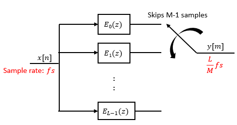
You can replace the upsampling operator, delay block, and the adder with a commutator switch. To account for the downsampler that follows, the switch moves in steps of size M. The switch receives the first sample from branch 0 and moves in the counter clockwise direction, each time skipping M−1 branches.
As an example, consider a rate converter with L set to 5 and M set to 3. The polyphase components are E0(z), E1(z), E2(z), E3(z), and E4(z). The switch starts on the first branch 0, skips branches 1 and 2, receives the next sample from branch 3, then skips branches 4 and 0, receives the next sample from branch 2, and so on. The sequence of branches from which the switch receives the data sample is [0, 3, 1, 4, 2, 0, 3, 1, ….].
The rate converter implements the L/M conversion by first applying the interpolation factor L to the incoming data, and using the commutator switch at the end to receive only 1 in M samples, effectively accounting for the downsampling factor M. Hence, the sample rate at the output of the FIR rate converter is Lfs/M.
References
[1] Orfanidis, Sophocles J. Introduction to Signal Processing. Upper Saddle River, NJ: Prentice-Hall, 1996.
Extended Capabilities
Version History
Introduced before R2006aSee Also
Functions
firceqrip|firgr|firnyquist
Objects
dsp.FIRRateConverter|dsp.FIRInterpolator|dsp.FIRDecimator|dsp.FIRHalfbandInterpolator|dsp.FIRHalfbandDecimator|dsp.CICCompensationInterpolator|dsp.CICCompensationDecimator