Get Started Communicating with the Unreal Engine Visualization Environment
R2026bThis example shows how to set up communication between Unreal Engine® and Simulink®. You create a cone actor in Unreal® Editor and use Simulink to set and get the cone location. You can set up communication with Unreal Engine by using the Simulation 3D Message Get and Simulation 3D Message Set blocks:
Simulation 3D Message Get receives data from the Unreal Engine environment.
Simulation 3D Message Set sends data to the Unreal Engine environment.
To use the blocks and communicate with Unreal Engine, make sure you install the Vehicle Dynamics Blockset™ Interface for Unreal Engine Projects support package. For more information, see Customize 3D Scenes for Vehicle Dynamics Simulations.
Next, follow these workflow steps to set up the Simulink model and the Unreal Engine environment and run a simulation.
| Workflow | Description | |
|---|---|---|
| Set Up Simulink Model to Send and Receive Data | Configure the Simulation 3D Message Get and Simulation 3D Message Set blocks in Simulink to send and receive the cone location from Unreal Editor. The steps provides the general workflow for communicating with the editor. The Simulation 3D
Message Get and Simulation 3D Message Set
blocks can send and receive these data types:
| |
Set Up Unreal Engine to Send and Receive Data | C++ Workflow: Set Up Unreal Engine to Send and Receive Data | Specific Unreal C++ workflow to send and receive Simulink cone location data.
To follow this workflow, you should be comfortable coding with C++ in Unreal Engine. Make sure that your environment meets the minimum software requirements described in Unreal Engine Simulation Environment Requirements and Limitations. |
| Blueprint Workflow: Set Up Unreal Engine to Send and Receive Data | Generalized Unreal Editor blueprint workflow to send and receive Simulink data. | |
| Run Simulation | After you set up the Simulink model and Unreal Editor environment, run a simulation. | |
Set Up Simulink Model to Send and Receive Data
Step 1: Install Support Package
If you have already downloaded and installed Unreal Engine and the Vehicle Dynamics Blockset Interface for Unreal Engine Projects support package, go to the next step.
To install and configure the support package, see Customize 3D Scenes for Vehicle Dynamics Simulations.
Before installing the support package, make sure that your environment meets the minimum software and hardware requirements described in Unreal Engine Simulation Environment Requirements and Limitations.
Note
Make sure to launch Unreal Engine from Simulink.
Step 2: Set Up Simulink Model
Open a new Simulink model. Connect the blocks as shown.
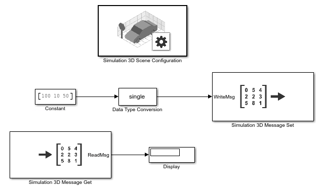
Step 3: Configure Blocks
Use these block settings to configure blocks to send and receive cone data from the Unreal Editor.
| Block | Parameter Settings |
|---|---|
Constant |
|
Simulation 3D Scene Configuration |
|
Simulation 3D Message Get |
|
| Simulation 3D Message Set |
|
C++ Workflow: Set Up Unreal Engine to Send and Receive Data
Step 4: Open Unreal Editor in Editor Mode
Create an Unreal Engine C++ project. Name it
TestSim3dGetSet. For steps on creating C++ projects, see Create Empty Project in Unreal Engine.In the Unreal Editor, on the Edit tab, select Plugins. Make sure that the
MathWorks Interfaceplugin checkbox is selected. If it is not, select it.Close the Unreal Editor.
If Visual Studio® is not open, open it.
In Visual Studio, add the
MathWorksSimulationdependency to theTestSim3dGetSetproject build file.In the Solution Explorer, the project build file,
TestSim3dGetSet.Build.cs, is located in this folder:...Games\TestSim3dGetSet\Source\TestSim3dGetSet.
In the build file, edit line 11 to add the
MathWorksSimulationdependency:PublicDependencyModuleNames.AddRange(new string[] { "Core", "CoreUObject", "Engine", "InputCore", "EnhancedInput", "MathWorksSimulation"});
Save the change and close the
TestSim3dGetSetproject.Close Visual Studio.
In your model, open the Simulation 3D Scene Configuration block.
Set Project to
Your_Project_path\TestSim3dGetSet.uprojectSelect Open Unreal Editor.
Step 5: Create Actor Class
In the Unreal Editor, on the Content Browser tab, under Settings, select Show Engine Content and Show Plugin Content.
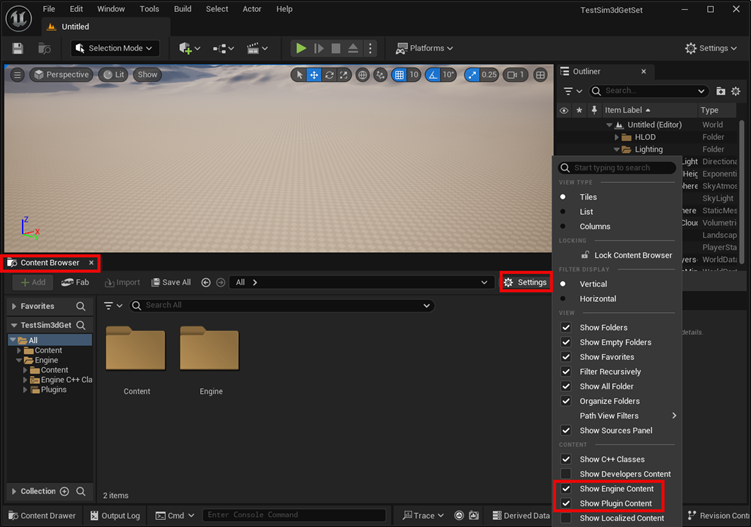
Tip
If the Content Browser is not in the Unreal Editor layout, click Content Drawer to display Content Browser and select Dock in Layout.
In the Unreal Editor, from the MathWorks Interface C++ classes directory, select Sim3dActor.
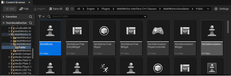
Right-click and select Create C++ class derived from Sim3dActor.

Name the new Sim3dActor
SetGetActorLocation. Select Public. Click Create Class.Close the Unreal Editor.
Step 6: Open SetGetActorLocation.h
Visual Studio opens with new C++ files in the project folder:
SetGetActorLocation.hSetGetActorLocation.cpp
Make sure you close the Unreal Editor.
In Visual Studio, build the solution TestSim3dGetSet:
In the Solution Explorer, under the Games folder, right-click TestSim3dGetSet.
Select Build.
After the solution builds, open
SetGetActorLocation.h. Edit the file as shown.
Step 7: Open SetGetActorLocation.cpp
Open SetGetActorLocation.cpp and replace the block of
code.
Step 8: Build the Visual Studio Project and Open Unreal Editor
In Visual Studio, select Debug > Start Debugging or press F5 to run the
TestSim3dGetSet solution. The Unreal Editor opens.
Note
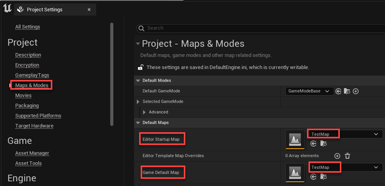
In the Unreal Editor, save the current level by clicking File > Save Current Level. Name the level TestMap. Add this level as the default to
Project Settings by clicking Edit > Project Settings > Maps&Modes. Then, select TestMap as the default value for the Editor
Startup Map and Game Default Map. To save the default values, close Project Settings.
Step 9: Place and Check Actor
In the Unreal Editor, find the Set Get Actor Location in the Place Actor icon, and place it in the
TestMap.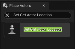
On the Outliner tab, check that the new instantiated actor,
SetGetActorLocation, is listed.
Step 10: Add Mesh
Click the actor that you created in Step 9: Place and Check Actor.
In the Details tab, click Add to add a mesh to the actor
SetGetActorLocation. ChooseConeas the default mesh.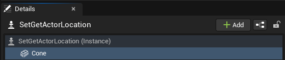
Find the property Tags for actor
SetGetActorLocation. Add a tag by clicking the plus sign next to 0 Array elements. Name itConeLoc.
Tip
For Simulink to communicate with the Unreal Engine environment, the C++ code appends
GetandSetto the tag name to match the Signal name parameter set in the Simulation 3D Message Get and Simulation 3D Message Set blocks.
Step 11: Set Cone Location
On the Details tab, click Cone. Set the
cone to X = 0.0, Y = 0.0, and Z =
0.0. Also set the actor Mobility
property to Movable.

Step 12: Set Parent Class and Save Scene
Set the parent class.
Under
 , click Open Level Blueprint.
Select Class Settings. In the Class Options, set Parent Class to
Sim 3d Level Script
                    Actor
.
Save the Unreal Editor scene.
Step 13: Run Simulation
To run the simulation, go to Run Simulation.
Reference: C++ Functions for Sending and Receiving Simulink Data
Call these C++ functions from Sim3dSetup, Sim3dStep, and Sim3dRelease to send and receive Simulink data.
Blueprint Workflow: Set Up Unreal Engine to Send and Receive Data
Step 4: Open Unreal Editor in Editor Mode
Create an Unreal Engine blueprint project. Name the project
TestSim3dGetSet. For steps on creating blueprint projects, see Create Empty Project in Unreal Engine.In the Unreal Editor, on the Edit tab, select Plugins. Make sure that the
MathWorks Interfaceplugin is enabled. If it is disabled, enable it and restart the Unreal Editor for your changes to take effect.Close the Unreal Editor.
In your model, open the Simulation 3D Scene Configuration block.
Set Project to
Your_Project_path\TestSim3dGetSet.uprojectSelect Open Unreal Editor.
In the Unreal Editor, save the current level by clicking File > Save Current Level. Name the level TestMap. Add this level as the default to
Project Settings by clicking Edit > Project Settings > Maps&Modes. Then, select TestMap as the default value for the Editor
Startup Map and Game Default Map. To save the default values, close Project Settings.
Step 5: Configure Scenes to Receive Data
To use the Simulation 3D Message Set block, you must configure scenes in the Unreal Engine environment to receive data from the Simulink model.
In the Unreal Editor, instantiate the
Coneactor.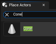
In the Details tab, set the actor Mobility property to
Movable.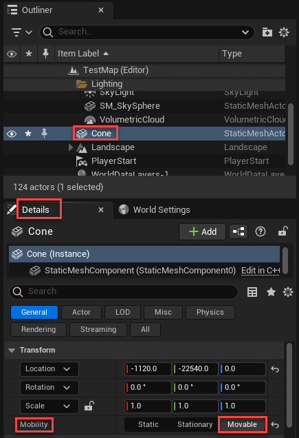
In the Details tab, add the
Sim3DSubscribercomponent to the cone. Components manage complex hierarchies and support double-precision data transmission.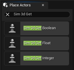
Click
Sim3DSubscriberin the Details tab and specify a value for Topic name that matches the Simulation 3D Message Set block Signal name parameter value. For this example, add the topic nameConeLocSet.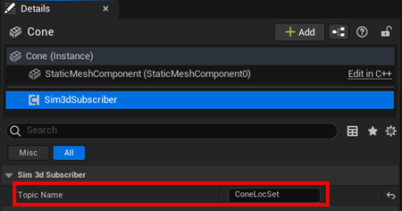
Navigate to the level blueprint.
Set the parent class.
Under
, click Open Level Blueprint.Select Class Settings. In the Class Options, set Parent Class to
Sim 3d Level Script
                    Actor
.
Set the game mode of the project to
Sim3dGameMode. In the Unreal Editor toolbar, select Edit > Project Settings > Project > Maps & Modes. SelectSim3dGameMode.Drag the cone to the level blueprint. Right-click the graph and find the blueprint method
Get
                                Component by Class
and set theComponent ClassasSim3DSubscriber. Click and drag from theReturn Valueoutput. From the list of blueprint method options, find the blueprint method based on the data type and size that you want to receive from the Simulink model.For this example, select
Read Vector FloatunderSim3DSubscriber.
Note
Depending on the number of elements you need to read, use one of these methods:
Read Scalar <DATA_TYPE>— Read one element.Read Vector <DATA_TYPE>— Read a vector of three elements.Read Array <DATA_TYPE>— Read an array of X elements.
Compile and save the scene.
Step 6: Configure Scenes to Send Data
To configure scenes in the Unreal Engine environment to send data to the Simulink model:
In the Unreal Editor, select the cone from the Outliner tab. In the Details tab, add the
Sim3DPublishercomponent to the cone.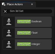
Specify the Topic name for
Sim3DPublisherthat matches the Simulation 3D Message Get block Signal name parameter value. For this example, add the topic nameConeLocGet.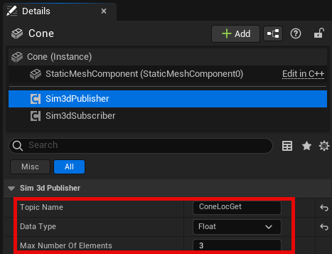
Navigate to the level blueprint.
Right-click the graph and find the blueprint method
Get Component by Classand setComponent ClassasSim3DPublisher. Click and drag from theReturn Valueoutput. From the list of blueprint method options, find the blueprint method based on the data type and size specified by the Simulation 3D Message Get block Data type and Message size parameters.For this example, select
Write Vector FloatunderSim3DPublisher.
Note
Depending on the number of elements you need to write, use one of these methods:
Write Scalar <DATA_TYPE>— Write one element.Write Vector <DATA_TYPE>— Write a vector of three elements.Write Array <DATA_TYPE>— Write an array of X elements.
Compile and save the scene.
Step 7: Create Blueprint
In the Unreal Editor, open the level blueprint to connect the components.
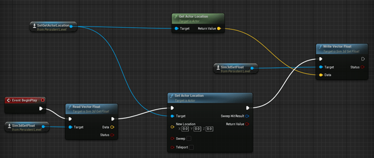
In the level blueprint, make the connections, this image shows example connections:
Step 8: Run Simulation
Run the simulation. Go to Run Simulation.
Run Simulation
After you configure the Simulink model and Unreal Editor environment, you can run the simulation.
In the Simulink model, click Run.
Because the source of the scenes is the project opened in the Unreal Editor, the simulation does not start.
Verify that the Diagnostic Viewer window in Simulink displays this message:
In the Simulation 3D Scene Configuration block, you set the scene
                    source to 'Unreal Editor'. In Unreal Editor, select 'Play' to view the
                    scene.
This message confirms that Simulink has instantiated the actors and other assets in the Unreal Engine 3D environment.
In the Unreal Editor, click Play. The simulation runs in the scene currently open in the Unreal Editor.
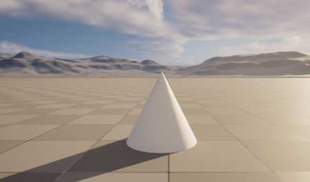
You can also change the value of the Constant block in the Simulink model during run time to see the corresponding cone location change in the Unreal Editor environment.
You can send and receive these data types: double,
single, int8, uint8,
int16, uint16, int32,
uint32, and boolean. The code in Step 7: Open SetGetActorLocation.cpp reads single data type
values (or float values) from Simulink.
See Also
ASim3dActor | Sim3dSetup | Sim3dStep | Sim3dRelease | Simulation 3D Scene Configuration | Simulation 3D Message Get | Simulation 3D Message Set
Topics
- Animate Custom Actors in the Unreal Editor
- Place Cameras on Actors in the Unreal Editor
- Send and Receive Double-Lane Change Scene Data

