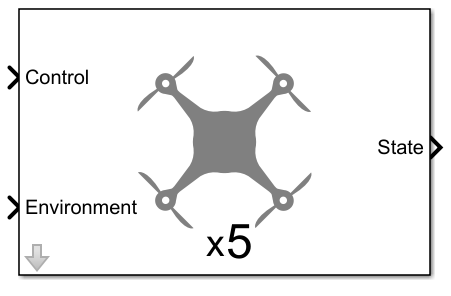
Multi-Instance Guidance Model
Libraries:
UAV Toolbox /
Algorithms
Description
Examples
Open the reducedOrderMultiUAVModel.slx Simulink® model. The model uses the Multi-Instance Guidance Model block to simulate multiple UAVs with reduced order fixed-wing kinematic models, and a UAV Animation block to visualize the result.
open_system("reducedOrderMultiUAVModel")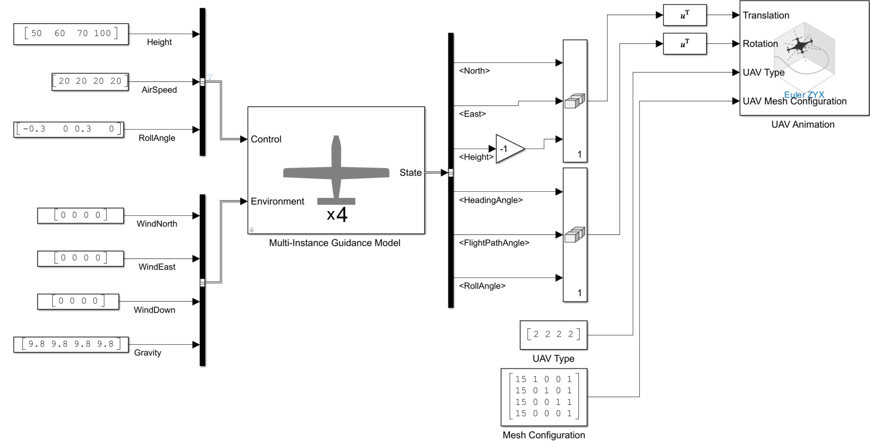
Initial Condition of UAV
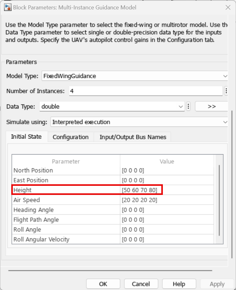
This model simulates the flight of four UAVs. Each UAV starts the simulation in the same position, air speed, heading angle, roll angle, and roll angle velocity. However, each UAV have different initial heights:
UAV 1 — 50 meters
UAV 2 — 60 meters
UAV 3 — 70 meters
UAV 4 — 80 meters
The initial condition is specified in the Initial State parameter of the Multi-Instance Guidance Model block.
Configuration of UAV
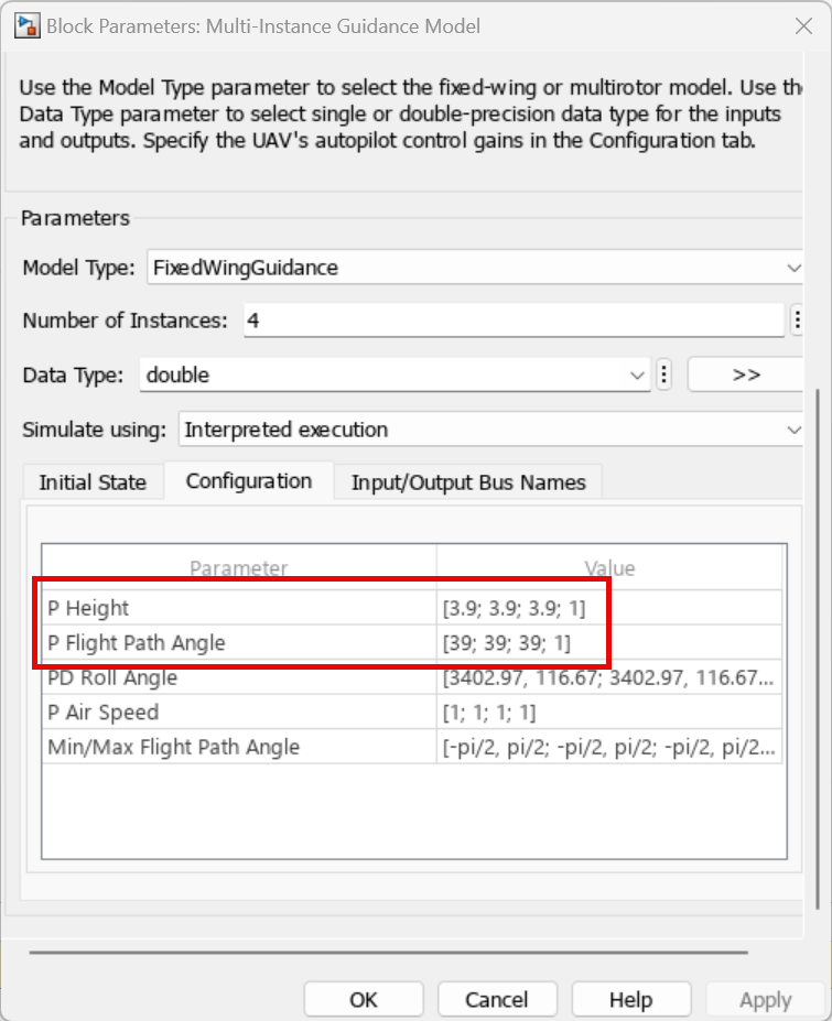
UAV 1, UAV 2, and UAV 3 are configured with default controller configuration. UAV 4 is configured with a proportional gain of the height controller of 1, and a proportional gain of the flight path angle controller of 1. This configuration is specified in the Configuration parameter of the Multi-Instance Guidance Model block.
Control Input
This model uses the Bus Creator block to create the control input bus. The bus name is specified in accordance with the Control Bus Name parameter of the Multi-Instance Guidance Model block.
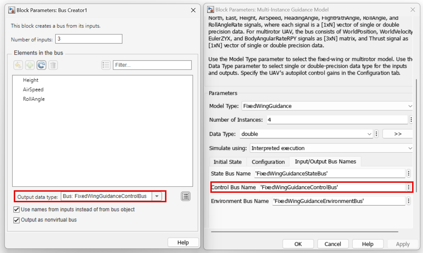
The bus contains these elements:
Height— Sets UAV 1, 2, 3, and 4 to have heights of 50, 60, 70, and 100 meters, respectively.AirSpeed— Sets all UAV to have an air speed of 20 m/s.RollAngle— Sets UAV 1, 2, 3, and 4 to have roll angles of -0.3, 0, 0.3, and 0 radians, respectively.
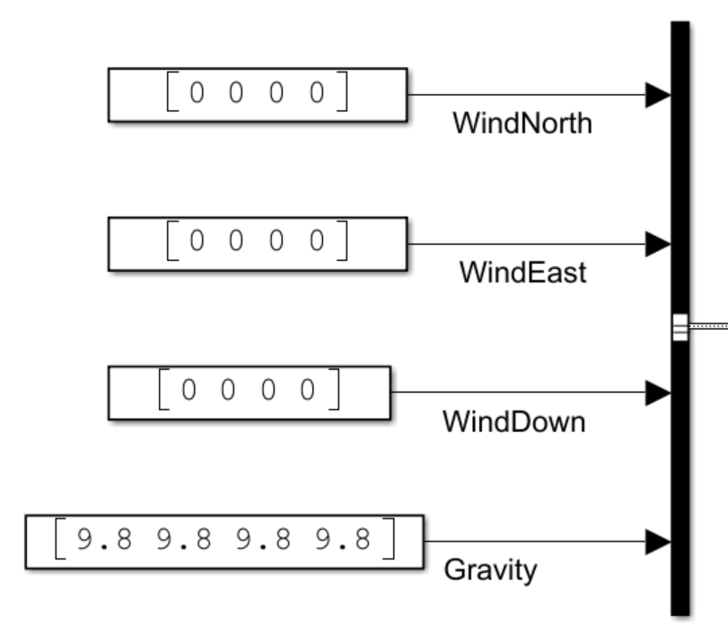
Environment Input
This model uses the Bus Creator block to create the environment input bus. The bus name is specified in accordance with the Environment Bus Name parameter of the Multi-Instance Guidance Model block.
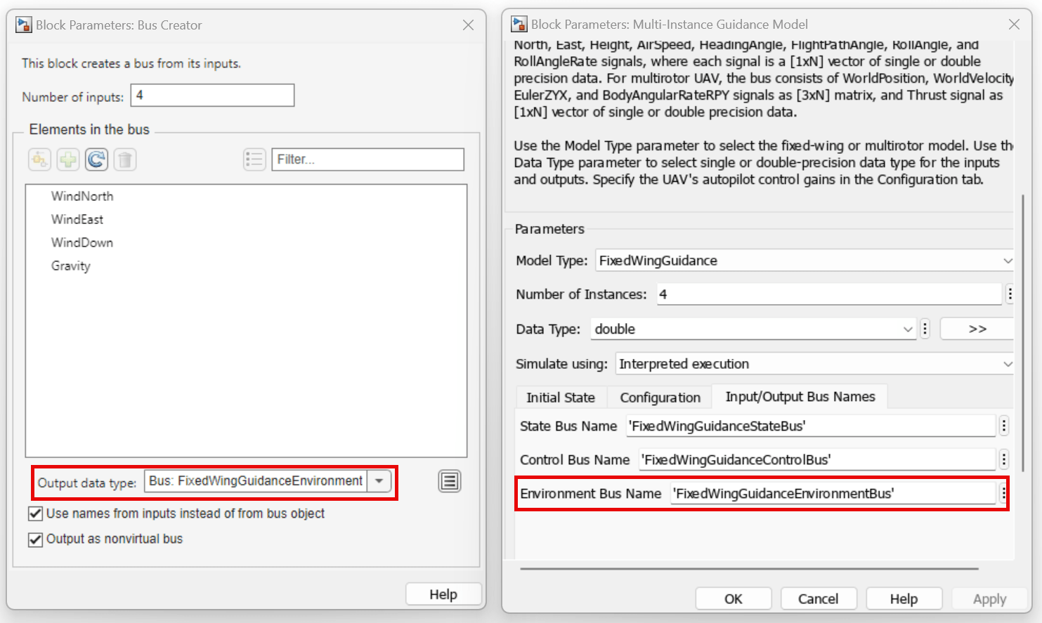
The bus contains the following elements:
WindNorth— Sets all UAV to have north wind velocities of 0 m/s.WindEast— Sets all UAV to have east wind velocities of 0 m/s.WindDown— Sets all UAV to have down wind velocities of 0 m/s.Gravity— Sets all UAV to have a gravitational accelerations of 9.8 m/s2.
Visualizing State Output
Before visualizing the state output, the model performs these operations on the elements of the bus output by the Multi-Instance Guidance Model block.
Multiplies the
<Height>signal by a gain of –1 to match the z-axis direction of the UAV Animation block. The model then combine the height signal with<North>and<East>signals into a matrix. The model transposes the matrix so that each row contains the translation of each UAV, and connects the matrix to the Translation port of the UAV Animation block.Combines the
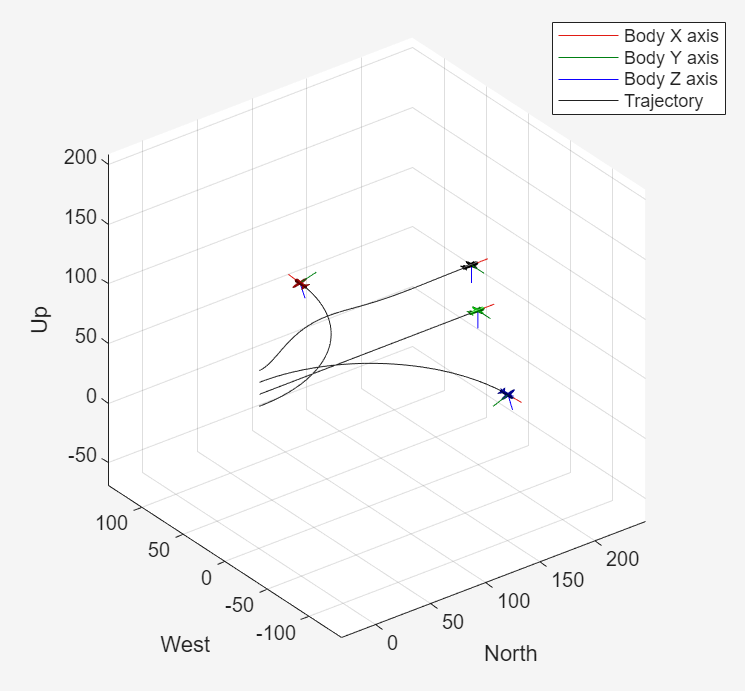
<HeadingAngle>,<FlightPathAngle>, and<RollAngle>signals into a matrix. The model transposes the matrix so that each row contains the rotation angle of each UAV, and connects the matrix to the Rotation port of the UAV Animation block.The vector specified to the UAV Type input of the UAV Animation block indicates that all three UAVs are fixed-wing, while the UAV Mesh Configuration input sets the colors of UAVs 1, 2, 3, and 4 to red, green, blue, and black, respectively.
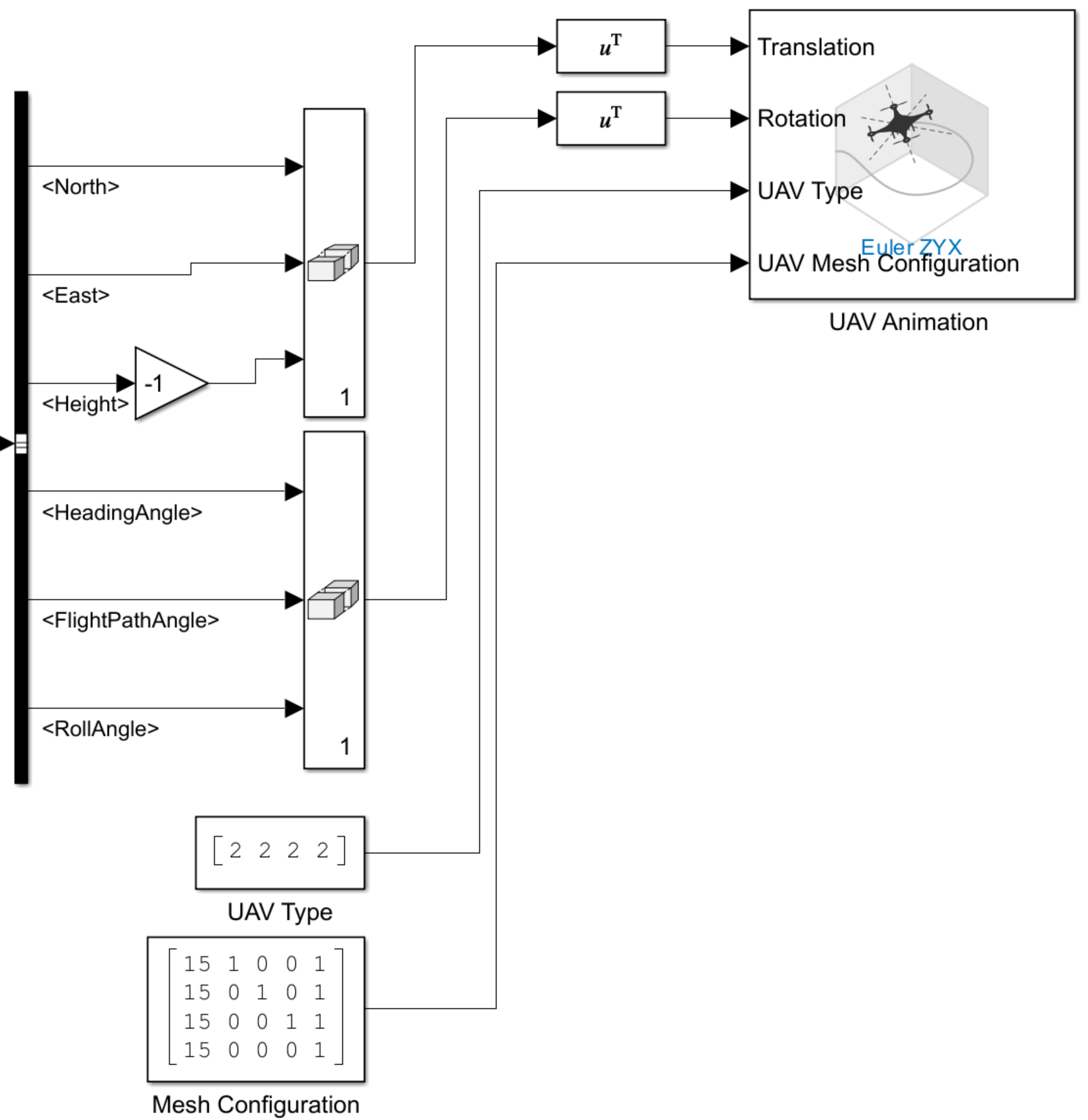
Run the Simulink model, and observe the simulation result from the UAV Animation window.
Ports
Input
Output
Parameters
More About
References
[1] Beard, Randal W., and Timothy W. McLain. “Design Models for Guidance.” In Small Unmanned Aircraft: Theory and Practice, 175–87. Princeton, NJ: Princeton University Press, 2012
[2] Mellinger, Daniel, Nathan Michael, and Vijay Kumar. “Trajectory Generation and Control for Precise Aggressive Maneuvers with Quadrotors.” The International Journal of Robotics Research 31, no. 5 (April 2012): 664–74. https://doi.org/10.1177/0278364911434236.
Extended Capabilities
Version History
Introduced in R2025a