Coordinate Systems in UAV Toolbox
This topic provides an overview of the coordinate systems that the UAV Toolbox uses in scenario simulation, flight log analysis, and motion planning, as well as for guidance, navigation, and control functionalities. For information on the specific coordinate systems that the UAV Toolbox uses for 3D simulation in the Unreal Engine® environment, see Coordinate Systems for Unreal Engine Simulation in UAV Toolbox.
Inertial Frame
The inertial frame is fixed to the Earth, and has zero linear and angular acceleration and zero angular velocity. UAV Toolbox uses these coordinate systems for the inertial frame:
North-East-Down (NED) Coordinate System — A north-east-down (NED) system uses the Cartesian coordinates
[xNorth yEast zDown]to represent position relative to a local origin. The local origin is described by the geodetic coordinates[lat0 lon0 alt0]wherelat0,lon0, andalt0are the latitude, longitude, and altitude of the local origin.The positive xNorth-axis points north along the meridian of longitude containing
lat0.The positive yEast-axis points east along the parallel of latitude containing
lon0.The positive zDown-axis points downward along the ellipsoid normal.

East-North-Up (ENU) Coordinate System — An east-north-up (ENU) system uses the Cartesian coordinates
[xEast yNorth zUp]to represent position relative to a local origin. The local origin is described by the geodetic coordinates[lat0 lon0 alt0]wherelat0,lon0, andalt0are the latitude, longitude, and altitude of the local origin.The positive xEast-axis points east along the parallel of latitude containing lat0.
The positive yNorth-axis points north along the meridian of longitude containing lon0.
The positive zUp-axis points upward along the ellipsoid normal.

Custom
You can also use the
uavScenarioobject to create an inertial frame with a custom coordinate system. The z-axis of the custom coordinate system must always point upward or downward. For more information, seeaddInertialFrame.Geodetic
A geodetic system uses the coordinates
[lat lon alt]to represent position relative to a reference ellipsoid. The UAV Toolbox uses the WGS84 reference ellipsoid.lat— Latitude originates at the Equator. The latitude of a point is the angle between a normal to the ellipsoid and the equatorial plane, which contains the center and Equator of the ellipsoid at that point. Angles of latitude must be in the range [–90°, 90°]. Positive latitudes correspond to north, and negative latitudes correspond to south.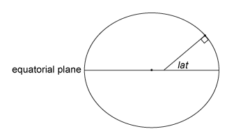
lon— Longitude originates at the prime meridian. The longitude of a point is the angle between two planes: one that contains the ellipsoid center and the meridian containing that point, and the other contains the ellipsoid center and prime meridian. Positive longitudes measure counterclockwise from a vantage point above the North Pole. Typically, longitude is within the range [–180°, 180°] or [0°, 360°].
alt— Altitude, or the ellipsoidal height measures along a normal of the reference ellipsoid.
Body Frame
The body frame is fixed and centered on the UAV center of mass. UAV Toolbox uses these coordinate systems for the body frame:
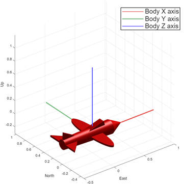
Front-Left-Up (FLU)
UAV Toolbox uses the FLU coordinate system if the z-axis of the inertial frame coordinate system points upwards, such as the ENU coordinate system.
In this coordinate system, the axes follow these conventions:
The x-axis points through the nose of the UAV.
The y-axis points perpendicular and to the left of the x-axis.
The z-axis points up, perpendicular to the xy plane.
In this plot, red, green, and blue lines show the x, y, and z-axes of the FLU coordinate system.
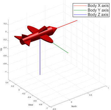
Front-Right-Down (FRD)
UAV Toolbox uses the FRD coordinate system if the z-axis of the inertial frame coordinate system points downwards, such as the NED coordinate system.
In this coordinate system, the axes follow these conventions:
The x-axis points through the nose of the UAV
The y-axis points perpendicular and to the right of the x-axis
The z-axis points down, perpendicular to the xy plane.
In this plot, red, green, and blue lines show the x, y, and z-axes of the FRD coordinate system
UAV Toolbox uses the frame rotation angles between the inertial frame and body frame in a ZYX (yaw-pitch-roll) rotation sequence to determine UAV orientation.
In addition, the body coordinate system defines sensor mounting location. For example, a mounting location of [1 0 1] for a UAV with an FLU body coordinate system places the sensor 1 meter ahead of, and 1 meter above the center of mass of the UAV.
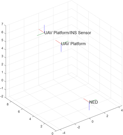
Sensor Frame
UAV Toolbox returns sensor readings in the sensor frame that is fixed to the sensor. UAV Toolbox defines the sensor frame by translating the body frame according to the sensor mounting location, and rotating the frame according to the sensor mounting angles.
For example, this plot shows the sensor frame generated by mounting an INS sensor 3
meters ahead of the UAV center of mass and rotating it 180 degrees around the
x-axis of the UAV body. In this plot, red, green, and blue
lines show the x, y, and
z-axes of each frame, respectively. This plot has been
generated by using a transformTree object.
Conversion Between Coordinate Systems
UAV Toolbox provides objects and functions that you can use to convert between coordinate systems. For more details, see Coordinate Transformations.