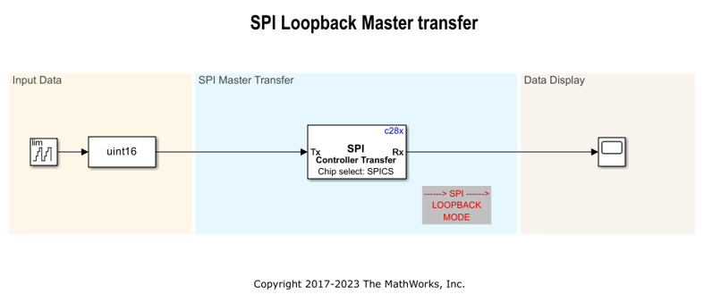
C28x SPI Controller Transfer
Write data to and read data from SPI peripheral device
Libraries:
C2000 Microcontroller Blockset /
C2802x
C2000 Microcontroller Blockset /
C2803x
C2000 Microcontroller Blockset /
C2805x
C2000 Microcontroller Blockset /
C2806x
C2000 Microcontroller Blockset /
C280x
C2000 Microcontroller Blockset /
C281x
C2000 Microcontroller Blockset /
C2833x
C2000 Microcontroller Blockset /
C2834x
C2000 Microcontroller Blockset /
F280013x
C2000 Microcontroller Blockset /
F280015x
C2000 Microcontroller Blockset /
F28002x
C2000 Microcontroller Blockset /
F28003x
C2000 Microcontroller Blockset /
F28004x
C2000 Microcontroller Blockset /
F2807x
C2000 Microcontroller Blockset /
F2837xD
C2000 Microcontroller Blockset /
F2837xS
C2000 Microcontroller Blockset /
F2838x /
C28x
C2000 Microcontroller Blockset /
F28M35x /
C28x
C2000 Microcontroller Blockset /
F28M36x /
C28x
C2000 Microcontroller Blockset /
F28p65x
C2000 Microcontroller Blockset /
F28p55x
Embedded Coder Support Package for STMicroelectronics STM32 Processors /
STM32F4xx Based Boards
Embedded Coder Support Package for STMicroelectronics STM32 Processors /
STM32F746G-Discovery
Embedded Coder Support Package for STMicroelectronics STM32 Processors /
STM32F769I-Discovery
Embedded Coder Support Package for STMicroelectronics STM32 Processors /
STM32F7xx Based Boards
Embedded Coder Support Package for STMicroelectronics STM32 Processors /
STM32G4xx Based Boards
Embedded Coder Support Package for STMicroelectronics STM32 Processors /
STM32H7xx Based Boards
Embedded Coder Support Package for STMicroelectronics STM32 Processors /
STM32L475VG-Discovery (B-L475E-IOT01A)
Embedded Coder Support Package for STMicroelectronics STM32 Processors /
STM32L4xx Based Boards
Embedded Coder Support Package for STMicroelectronics STM32 Processors /
STM32L5xx Based Boards
Embedded Coder Support Package for STMicroelectronics STM32 Processors /
STM32U5xx Based Boards
Embedded Coder Support Package for STMicroelectronics STM32 Processors /
STM32WBxx Based Boards
Simulink Coder Support Package for STMicroelectronics Nucleo Boards /
Common
Simulink Support Package for Raspberry Pi Hardware /
Communication
Description
The C28x SPI Controller Transfer block writes data to and reads data from a peripheral device over the Serial Peripheral Interface (SPI). The block runs in controller mode. The block outputs an array of the same size and data type as the input values. You can use this block with the Byte Pack and Byte Unpack blocks for heterogeneous data type transfers.
Note
To communicate with multiple peripherals using the same SPI module, use multiple instances of the SPI block with the same module and configure a unique chip select for each instance.
Configure the SPI modules for the specific hardware board by navigating to Hardware Implementation > Target hardware resources. Verify that these settings meet the requirements of your application.
Using this block, you can access an SPI device to measure quantities such as temperature and pressure.
Examples
Using SPI to Read and Write Data to SPI EEPROM
Configure and use SPI blocks to read and write data.
Ports
Input
Output
Parameters
Extended Capabilities
Version History
Introduced in R2017b
See Also
C28x SPI Receive | C28x SPI Transmit | C28x Hardware Interrupt