Tune PID Controller for Vehicle Lateral Control System Using Virtual Reference Feedback Tuning Block
This example shows how to use the Virtual Reference Feedback Tuning (VRFT) block to tune a PID controller for a more realistic nonlinear plant model. The example demonstrates VRFT controller tuning for a vehicle lateral control system, as introduced by Dr. Suzuki in [1].
Vehicle Lateral Control Plant Model
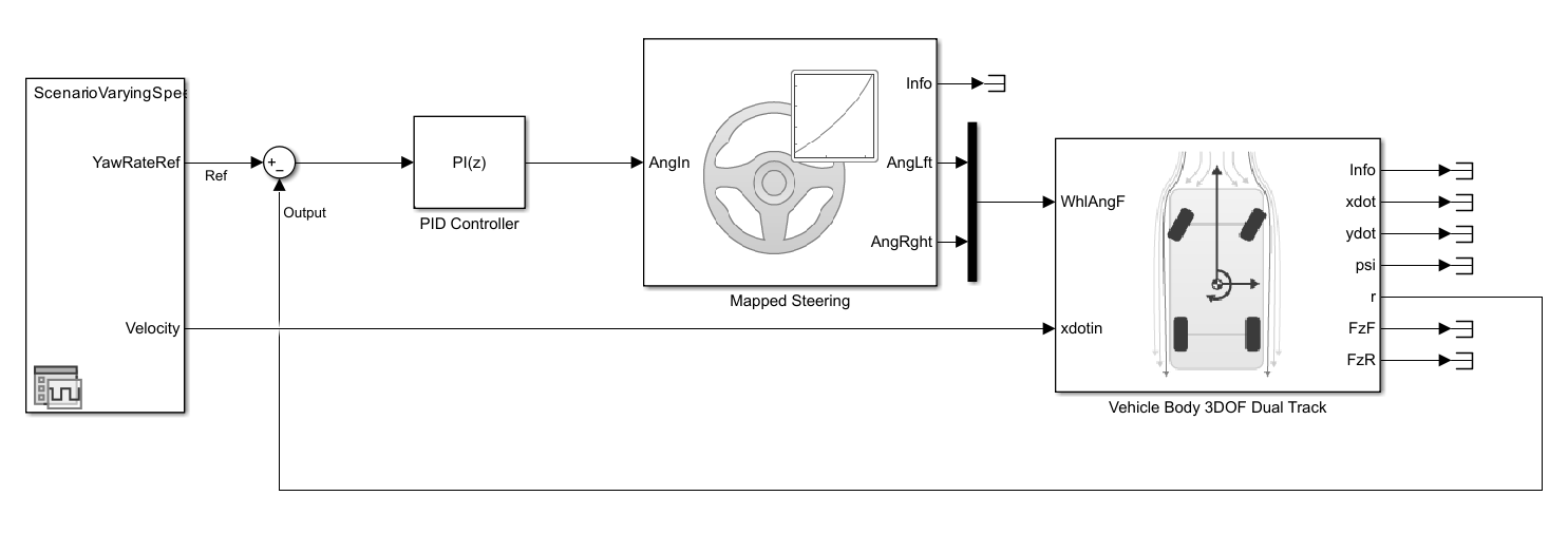
The goal of a lateral control system is to control the steering angle of a vehicle to follow a yaw-rate reference signal at different speed levels. The VDBLateralControlBasicDemo model is constructed using blocks from the Vehicle Dynamics Blockset™.
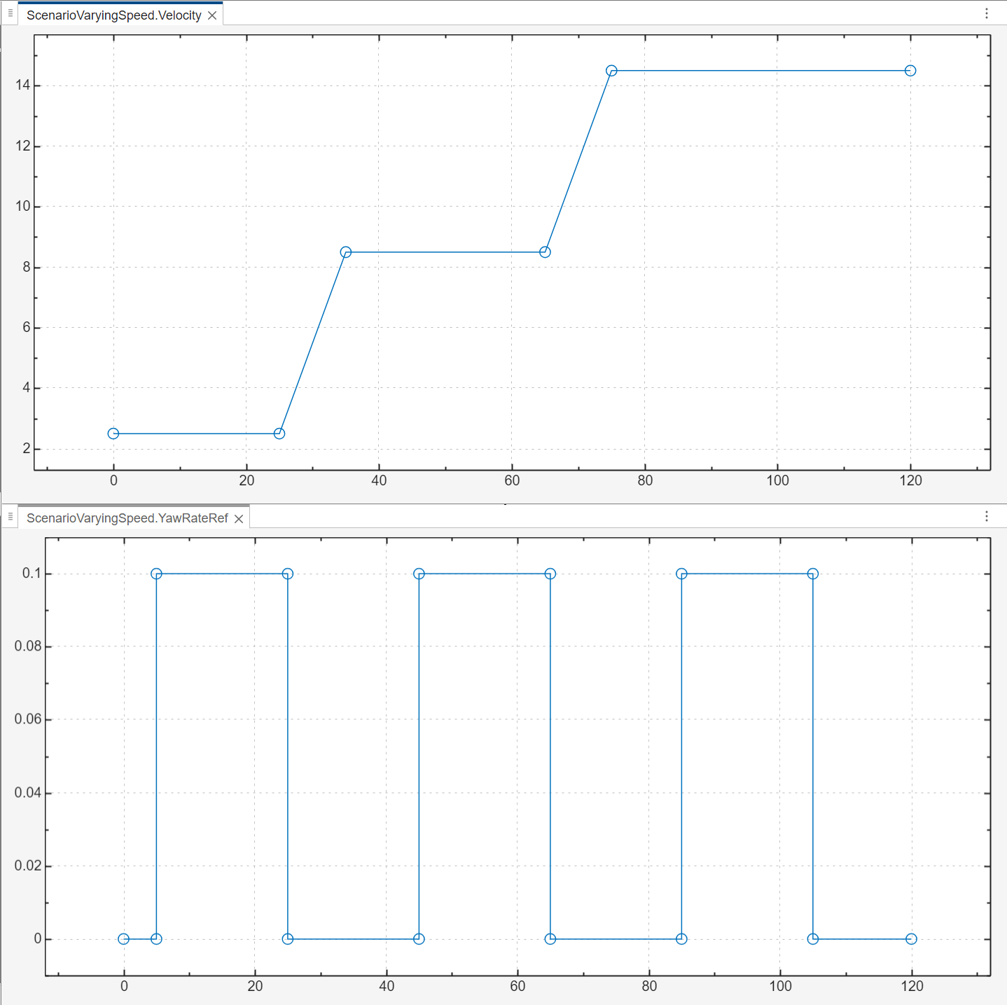
Both speed and yaw-rate reference signals are plotted in the following screenshot. While the vehicle's speed settles at a certain level, its yaw-rate is expected to follow the same square-wave signal regardless of the speed.
Closed-Loop Model with VRFT Tuning
Open the Simulink® model that includes the vehicle lateral control system as the plant model and the VRFT block preconfigured for tuning.
mdl = 'VDBLateralControlVRFTDemo.slx';
open_system(mdl);
This model includes an initial PI controller that regulates the output. The performance is not ideal and corresponds to a slow turning behavior. The initial controller gains are Kp = 12 and Ki = 6.
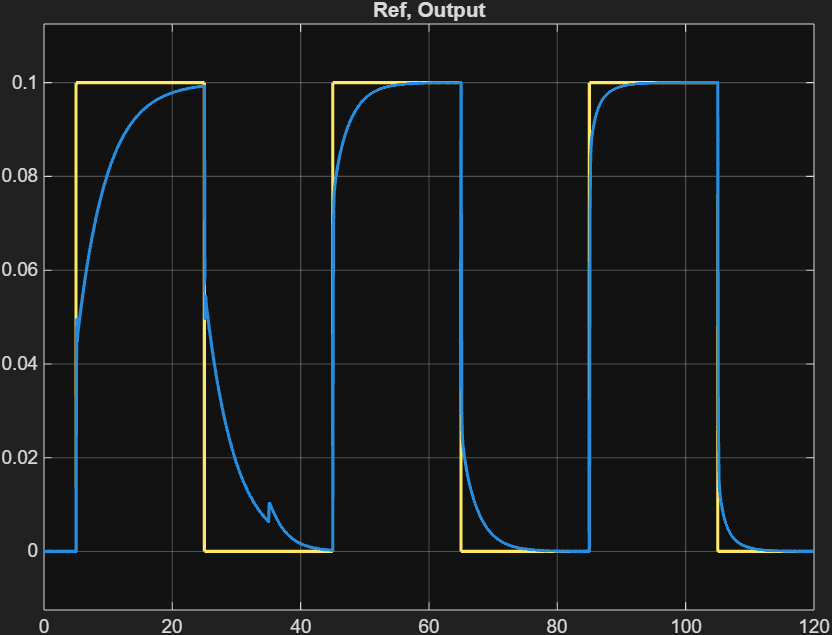
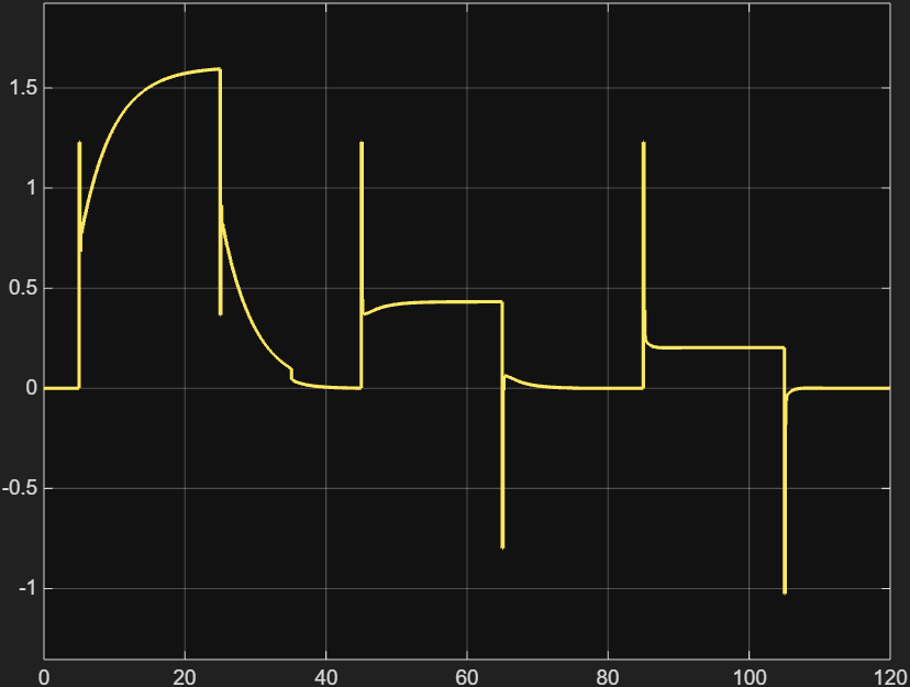
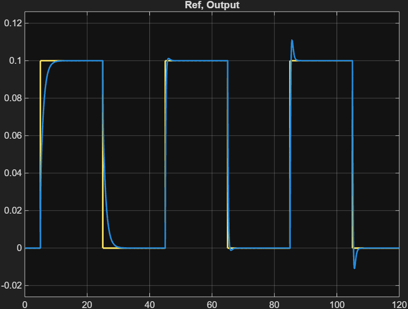
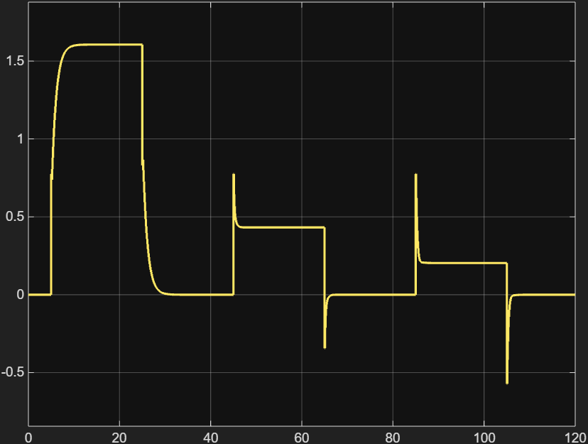
The first plot shows the comparison between the reference yaw rate and the actual output from the vehicle dynamics model. It is obvious that the yaw rate does not follow square-wave reference signal closely at low-speed. To achieve this performance, however, the steering angle in the second plot shows large peaks that would be difficult to achieve using a steering wheel. As a result, the lateral control system has room for improvement to track the reference yaw-rate at different speed levels.
Tuning the PI controller is straightforward using the VRFT block. The reference model is the most important parameter. This example uses a transfer function tf(1,[0.2 1]) as the reference model. The weighting function is set to tf(1,[0.01 1]) to focus the tuning over a lower frequency range. The model is set up to update the PI controller gains after the tuning process finishes. As opposed to the PID autotuner blocks, VRFT does not inject any additional perturbation signals into the plant model for system identification purposes.
SimOut = sim(mdl);
PIDGains = SimOut.ScopeData.signals.values;
Kp = PIDGains(1)
Kp =
6.7302
Ki = PIDGains(2)
Ki =
20.5267
Using the tuned PI controller gains with the original model VDBLateralControlBasicDemo, the yaw-rate follows the reference signal much faster across different speed levels. At the same time, the steering angles has a much smaller peak compared to the original PI controller.
Close the current Simulink model without any changes.
close_system(mdl,0);
In this example, you used the Virtual Reference Feedback Tuning (VRFT) block to tune a PI controller for a more realistic vehicle lateral control system. Using the steering angle and yaw-rate measurement data sequences collected from the plant model in a closed-loop configuration, the VRFT block improved the performance of the existing vehicle lateral controller without breaking its feedback loop. The tuning process covers steering operations over different speed levels. This ensures that the tuned gains achieve satisfactory control performance with changing speeds. Additionally, this data-driven tuning method can provide better tuning results compared to traditional model-based tuning methods at different operating points.
References
[1] Motoya Suzuki, Isuzu Advanced Engineering Center. “Automated Generation of Lateral Motion Controllers for Autonomous Trucks Using Data-Driven Control.” MATLAB EXPO, Japan, 2022. https://www.mathworks.com/company/user_stories/isuzu-advanced-engineering-center-develops-automatic-lateral-motion-controller-generation-tool-for-automated-trucks.html.
See Also
Virtual Reference Feedback Tuning