Create Model Components
As you gather requirements for a system, you identify model components. While you might not have complete specifications, you likely have an idea of where the component interfaces belong. To organize a model into model components with flexible interfaces, create subsystems.
Some components, such as digital controllers, should execute as a single unit within the model. For these standalone components with known boundaries, create an atomic subsystem. Defining atomic components upfront prevents costly refactoring when you want to generate standalone code. To make a subsystem atomic, select a Subsystem block. In the Simulink® Toolstrip, on the Subsystem Block tab, select Make Atomic.
The model named BasicModelingSubsystems contains four common model components.
Plant — Mathematical model of a system
Controller — Algorithm that controls the behavior of the plant
Operator — Logic that defines the commands sent to the controller
Environment — External disturbances that affect the plant
mdl = "BasicModelingSubsystems";
open_system(mdl)
The thick border of the Subsystem block named Controller indicates that the corresponding subsystem is an atomic subsystem.
The ports on each Subsystem block correspond to input and output blocks within the subsystem. For example, the Subsystem block named Plant has a port named control that corresponds with an In Bus Element block labeled control in the subsystem.

In this example, the plant represents a mass-spring-damper system.
The controller computes the force required to move the plant to its goal position.

The operator determines the goal position of the mass and implements the related procedural logic with a Stateflow® chart.

The environment generates a disturbance force that affects the plant.
![]()
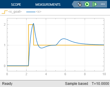
The model components interact to determine the position of the mass.
During simulation, the operator tells the controller to wait 2 seconds, then move the mass up 2 meters. When the mass overshoots the goal position, the operator tells the controller to position the mass 1 meter above its original position. After 5 seconds, an environmental disturbance applies a steady force to the physical system and the controller reacts to stabilize the mass at the goal position.
sim(mdl);
