Create Nonvirtual Buses
A nonvirtual bus is analogous to a structure in C code. Use nonvirtual buses to:
Construct an array of buses.
Have bus data cross MATLAB Function block or Stateflow® chart boundaries.
Package bus data as structures in generated C code.
Interface with external code through an S-function.
Reduce the number of function arguments passed to a subcomponent in generated code.
A Simulink.Bus object data type must define the
bus you want to make nonvirtual. A bus becomes nonvirtual when you select a block parameter
such as Output as nonvirtual bus. Making the bus nonvirtual causes
simulation and code generation to apply the structure defined by the bus
object. When the bus is virtual, the bus object only validates the properties
of the bus.
To simulate a model that contains nonvirtual buses, the referenced bus objects must be in the base workspace or a data dictionary used by the model. For more information, see Define Bus Properties for Reuse.
Nonvirtual buses also require all elements of the bus to have the same sample time. For more information, see Modify Sample Times for Nonvirtual Buses.
The way to create nonvirtual buses differs based on the location of the bus and the block that creates the bus:
To focus on fundamental steps, the examples are simple. However, buses are most useful when you have many signals to combine.
Create Nonvirtual Buses Within Component
You can use Bus Creator blocks to create nonvirtual buses within components.
Open and compile the model named BusHierarchy, which uses Bus Creator blocks to create a hierarchy of virtual buses. To compile the model, on the Modeling tab of the Simulink® Toolstrip, click Update Model or Run. Compiling the model updates the line styles, which you can use to visually identify buses.
Alternatively, in the MATLAB® Command Window, enter these commands.
mdl = "BusHierarchy";
open_system(mdl)
set_param(mdl, SimulationCommand="Update")
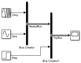
The virtual buses in this model are not defined by Simulink.Bus objects. To create nonvirtual buses, you must specify bus objects that match the bus hierarchy.
To create the bus objects interactively:
Open the Type Editor. Double-click a Bus Creator block. Then, next to the Output data type box, click
 .
.In the Type Editor, create two bus object by clicking
 .
.In each bus object, create two elements by clicking
 .
.Optionally, double-click and rename the objects. For this example, use the signal and bus names.
Set the data type of the
NestedBuselement toNestedBus.
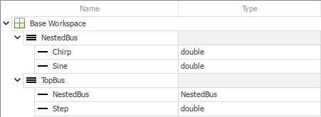
Alternatively, use the Simulink.Bus.createObject function.
bctop = "BusHierarchy/Bus Creator1";
Simulink.Bus.createObject(mdl,bctop);
The function creates two bus objects that are named after the corresponding buses, TopBus and NestedBus.
Now that you have bus objects that correspond to the nonvirtual buses you want to create, convert the top bus to a nonvirtual bus by updating the corresponding Bus Creator block parameters.
Open the Property Inspector. In the Simulink Toolstrip, on the Simulation tab, in the Prepare gallery, select Property Inspector.
Select the Bus Creator block named
Bus Creator1.In the Property Inspector, set Output data type to
Bus: TopBus.In the Property Inspector, select Output as nonvirtual bus.
To identify the nonvirtual bus by line style, recompile the model.
Alternatively, enter these commands.
set_param(bctop, OutDataTypeStr="Bus: TopBus")
set_param(bctop, NonVirtualBus="on")
set_param(mdl, SimulationCommand="Update")
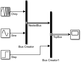
TopBus is now a nonvirtual bus, while NestedBus remains a virtual bus.
To convert the nested bus to a nonvirtual bus, update the corresponding Bus Creator block parameters:
Select the Bus Creator block named
Bus Creator.In the Property Inspector, set Output data type to
Bus: NestedBus.In the Property Inspector, select Output as nonvirtual bus.
To identify the nonvirtual bus by line style, recompile the model.
Alternatively, enter these commands.
bcnested = "BusHierarchy/Bus Creator";
set_param(bcnested, OutDataTypeStr="Bus: NestedBus")
set_param(bcnested, NonVirtualBus="on")
set_param(mdl, SimulationCommand="Update")
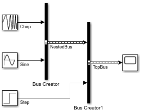
NestedBus is now a nonvirtual bus.
If you do not save the bus objects, you must recreate the bus objects when you reopen the model. For information on how to save the bus objects, see Define Bus Properties for Reuse.
Create Nonvirtual Buses at Interfaces
To create a nonvirtual bus at an interface, connect the bus elements to Out Bus Element blocks and specify that the output bus is nonvirtual.
Open the model named BusOutput, which uses three Out Bus Element blocks to create a virtual bus at the output port.
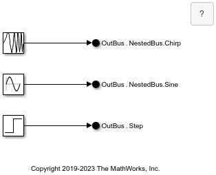
To create this model, see Connect Multiple Output Signals to One Port.
Nonvirtual buses require a Simulink.Bus object data type. Create the bus object that corresponds to the output bus.
In the Simulink® Toolstrip, on the Modeling tab, in the Design gallery, select Type Editor.
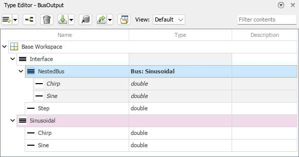
In the Type Editor, create bus objects named
InterfaceandSinusoidal.For each bus object, create the
Simulink.BusElementobjects that correspond to the elements of the buses. InSinusoidal, create elements namedChirpandSine. InInterface, create elements namedNestedBusandStep.Specify a bus object data type for any nested buses. For
NestedBus, set Data type toBus: Sinusoidal.
To output a nonvirtual bus, specify the bus object data type and bus virtuality.
Open the dialog box for the port by double-clicking one of the Out Bus Element blocks.
In the tree hierarchy of the dialog box, select
OutBus.To display the corresponding attributes, click
 .
.Set Data type to
Bus: Interface.Set Bus virtuality to
nonvirtual.

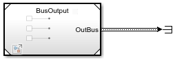
The output of the model is a nonvirtual bus. To see the nonvirtual bus, reference the model in another model or move the Out Bus Element blocks into a subsystem. The line styles update when you compile the model. To compile the model, on the Modeling tab of the Simulink Toolstrip, click Update Model or Run.
If you do not save the bus objects, you must recreate the bus objects when you reopen the model. For information on how to save the bus objects, see Define Bus Properties for Reuse.
In Bus Element blocks use the Bus virtuality parameter to determine whether they inherit or define the bus virtuality. If the block defines the bus virtuality and the virtuality of the input bus does not match, compiling the model produces an error.
Root Inport and Outport blocks can also create nonvirtual buses at interfaces. To specify the bus virtuality:
For a root Inport block, on the Signal Attributes tab of the dialog box, select Output as nonvirtual bus.
For a root Outport block, on the Signal Attributes tab of the dialog box, select Output as nonvirtual bus in parent model.
Convert Virtual Bus to Nonvirtual Bus
You can convert a virtual bus to a nonvirtual bus anywhere within a model by using a Signal Conversion block.
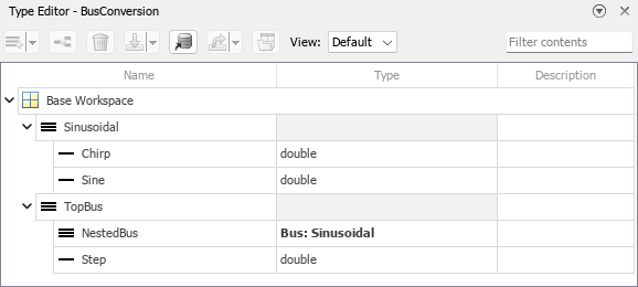
Open and compile the model named BusConversion, which contains a virtual bus hierarchy created by Bus Creator blocks. To compile the model, on the Modeling tab of the Simulink Toolstrip, click Update Model or Run. Compiling the model updates the line styles, which you can use to visually identify buses.

To define the buses and support conversion to nonvirtual buses, the Bus Creator blocks specify Simulink.Bus object data types. To create the bus objects in the base workspace when the model is loaded, the model uses the PreLoadFcn callback.
To view the callback, in the Simulink Toolstrip, on the Modeling tab, click Model Settings > Model Properties. In the Model Properties dialog box, open the Callbacks tab and select the PreLoadFcn model callback.
To view the bus objects, open the Type Editor.
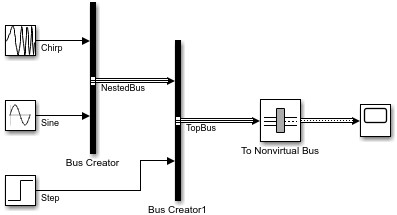
To convert a virtual bus to a nonvirtual bus, use a To Nonvirtual Bus block, which is a preconfigured version of the Signal Conversion block that has Output set to Nonvirtual bus.
In the example model:
Add a To Nonvirtual Bus block to the model.
Drag the To Nonvirtual Bus block onto the line between the Bus Creator block named
Bus Creator1and the Scope block. When you drag the block onto the line, the block connects to the line at both ends.
Suppose the data type of the bus you want to convert is not specified by a bus object. You would need to perform these additional actions:
Create the corresponding bus objects.
Specify the bus object data type for the bus. For example, set the Data type parameter of the To Nonvirtual Bus block to the bus object that corresponds to the input bus.
The input to the To Nonvirtual Bus block is a virtual bus, and the output is a nonvirtual bus. To see the nonvirtual bus line style, compile the model.
Create Nonvirtual Bus from MATLAB Structure
You can use a Constant block to compactly represent a nonvirtual bus with constant-valued elements.
On the Constant block:
Set Constant value to a MATLAB structure.
Set Output data type to a
Simulink.Busobject.
Constant blocks support MATLAB structures only when the output data type is a bus object.
Open and compile the example model, which contains a Constant block that creates a nonvirtual bus. Compiling the model updates the line styles, which you can use to visually identify buses. To compile the model, on the Modeling tab of the Simulink Toolstrip, click Update Model or Run. Alternatively, in the MATLAB Command Window, enter these commands.
mdl = "NonvirtualBusFromStructure";
open_system(mdl)
set_param(mdl,SimulationCommand="Update");

The PreLoadFcn model callback defines a MATLAB structure named busval with elements named offset, gain, and threshold. Then, the model callback uses the Simulink.Bus.createObject function to create a Simulink.Bus object from the structure. The bus object uses the default name slBus1.
To view the model callback, in the Simulink Toolstrip, on the Modeling tab, in the Design gallery, select Property Inspector. Model callbacks appear in the Property Inspector when nothing is selected at the top level of a model. Alternatively, to get the model callback programmatically, use the get_param function.
cb = get_param(mdl,"PreLoadFcn")cb =
'% Define a MATLAB structure named busval with elements named
% offset, gain, and threshold.
busval.offset = 197;
busval.gain = 4.32;
busval.threshold = 795.68;
% Define the corresponding Simulink.Bus object.
clear slBus1
Simulink.Bus.createObject(busval)'
To create a nonvirtual bus, the Constant block sets Constant value to busval and Output data type to Bus: slBus1.