Bus Creator
Group input signals, buses, or messages into bus
Libraries:
Simulink /
Commonly Used Blocks
Simulink /
Signal Routing
HDL Coder /
Signal Routing
Description
The Bus Creator block combines input signals, buses, or messages into a bus, which retains the separate identities of the signals, nested buses, and messages. By default, the Bus Creator block creates a virtual bus, which is analogous to a bundle of wires held together by tie wraps. Alternatively, the block can create a nonvirtual bus, which is analogous to a structure in C code.
Elements of a bus must have unique names. By default, each element of the bus inherits
the name of the element connected to the Bus Creator block. If duplicate
names are present, the Bus Creator block appends the port number to all
input element names. For elements that do not have names, the Bus Creator
block generates names in the form signaln, where n
is the port number connected to the element. You can refer to elements by name when you
search for their sources or select elements for connection to other blocks. For element
naming guidelines, see Signal Names and Labels.
To extract elements from the bus by name, use a Bus Selector block.
To create a bus that contains other buses, connect the other buses to the Bus Creator block input ports.
Tip
For buses at subsystem and model interfaces, use Out Bus Element blocks instead of a Bus Creator block with an Outport block. Out Bus Element blocks:
Reduce line complexity and clutter in a block diagram.
Allow you to more easily change the interface incrementally.
Examples
You can group signals into a virtual bus within a component by using Bus Creator blocks.
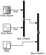
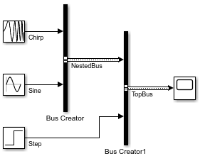
Open a new model and add three source blocks. For example, add a Chirp Signal, Sine Wave, and Step block.
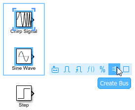
To create a bus that contains the outputs from multiple blocks, click and drag to select the blocks. For this example, select the Chirp Signal and Sine Wave blocks. In the action bar that appears, click Create Bus.
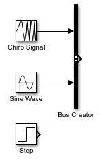
The software adds a Bus Creator block and connects the inputs to that block. The output of the Bus Creator block is a virtual bus.
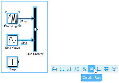
To make identifying the elements of the bus easier, label the inputs to the Bus Creator block.
Double-click the line between the Chirp Signal block and the Bus Creator block. Then, enter
Chirp.Double-click the line between the Sine Wave block and the Bus Creator block. Then, enter
Sine.
To create a second bus that contains the first bus and the output of the Step block, click and drag to select the Bus Creator and Step blocks. In the action bar that appears, click Create Bus. Including the Sine Wave and Chirp Signal blocks in your selection does not affect the result because these blocks provide elements of the input bus.
The software adds another Bus Creator block and connects the inputs to that block. The output of the Bus Creator block is a virtual bus that contains a nested bus.
You can nest buses to any depth. If one of the inputs to a Bus Creator block is a bus, then its output is a bus hierarchy that contains at least one nested bus.
Label the inputs to the new Bus Creator block.
Double-click the line between the Bus Creator blocks. Then, enter
Sinusoidal.Double-click the line between the Step block and the Bus Creator block. Then, enter
Step.
Optionally, arrange the blocks to improve the readability of the model.
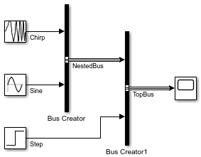
Connect the output of the second Bus Creator block to a
Scope block and label the output Sources.
To visually identify the buses by line styles, in the Simulink® Toolstrip, on the Modeling tab, click Update Model or Run.

You can use Bus Creator blocks to create nonvirtual buses within components.
Open and compile the model named BusHierarchy, which uses Bus Creator blocks to create a hierarchy of virtual buses. To compile the model, on the Modeling tab of the Simulink® Toolstrip, click Update Model or Run. Compiling the model updates the line styles, which you can use to visually identify buses.
Alternatively, in the MATLAB® Command Window, enter these commands.
mdl = "BusHierarchy";
open_system(mdl)
set_param(mdl, SimulationCommand="Update")
The virtual buses in this model are not defined by Simulink.Bus objects. To create nonvirtual buses, you must specify bus objects that match the bus hierarchy.
To create the bus objects interactively:
Open the Type Editor. Double-click a Bus Creator block. Then, next to the Output data type box, click
 .
.In the Type Editor, create two bus object by clicking
 .
.In each bus object, create two elements by clicking
 .
.Optionally, double-click and rename the objects. For this example, use the signal and bus names.
Set the data type of the
NestedBuselement toNestedBus.
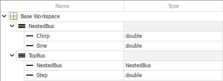
Alternatively, use the Simulink.Bus.createObject function.
bctop = "BusHierarchy/Bus Creator1";
Simulink.Bus.createObject(mdl,bctop);
The function creates two bus objects that are named after the corresponding buses, TopBus and NestedBus.
Now that you have bus objects that correspond to the nonvirtual buses you want to create, convert the top bus to a nonvirtual bus by updating the corresponding Bus Creator block parameters.
Open the Property Inspector. In the Simulink Toolstrip, on the Simulation tab, in the Prepare gallery, select Property Inspector.
Select the Bus Creator block named
Bus Creator1.In the Property Inspector, set Output data type to
Bus: TopBus.In the Property Inspector, select Output as nonvirtual bus.
To identify the nonvirtual bus by line style, recompile the model.
Alternatively, enter these commands.
set_param(bctop, OutDataTypeStr="Bus: TopBus")
set_param(bctop, NonVirtualBus="on")
set_param(mdl, SimulationCommand="Update")
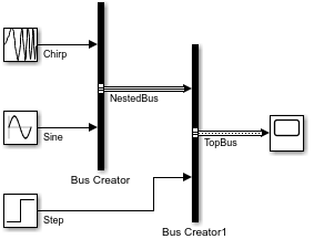
TopBus is now a nonvirtual bus, while NestedBus remains a virtual bus.
To convert the nested bus to a nonvirtual bus, update the corresponding Bus Creator block parameters:
Select the Bus Creator block named
Bus Creator.In the Property Inspector, set Output data type to
Bus: NestedBus.In the Property Inspector, select Output as nonvirtual bus.
To identify the nonvirtual bus by line style, recompile the model.
Alternatively, enter these commands.
bcnested = "BusHierarchy/Bus Creator";
set_param(bcnested, OutDataTypeStr="Bus: NestedBus")
set_param(bcnested, NonVirtualBus="on")
set_param(mdl, SimulationCommand="Update")
NestedBus is now a nonvirtual bus.
If you do not save the bus objects, you must recreate the bus objects when you reopen the model. For information on how to save the bus objects, see Define Bus Properties for Reuse.
Extended Examples

Simulink Bus Capabilities
Work with buses in components, simplify component interfaces, and streamline common bus workflows.
Ports
Input
Output
Parameters
To edit block parameters interactively, use the Property Inspector. From the Simulink Toolstrip, on the Simulation tab, in the Prepare gallery, select Property Inspector.
To create a bus, the number of block inputs must be an integer greater than or equal to 2.
Increasing the number of inputs adds unconnected input ports to the block. Before you simulate the model, make sure that an input connects to each input port.
If each input port is already connected, you can add an input port to the Bus Creator block by connecting another line to it.

Interactively adding a port updates the Number of inputs parameter value and adds the new input to the Inputs list.
Programmatic Use
To set the block parameter value programmatically, use
the set_param function.
Specify the number of inputs as an integer greater than or equal to 2.
| Parameter: | Inputs |
| Values: | '2' (default) | integer in quotes |
| Data Types: | char | string |
Example: set_param(gcb,
Inputs="3")
The Inputs list provides the elements that enter the block, including the elements of nested buses. An arrow next to an element indicates that an input is a bus. To display the contents of that bus, click the arrow.
To reorder the input elements, select one or more top-level elements from the Inputs list. Then, drag the elements to a new position.
To add or remove input elements, click ![]() or
or ![]() , respectively. Before you simulate the
model, make sure that each input port is connected.
, respectively. Before you simulate the
model, make sure that each input port is connected.
To refresh the list of input elements, click ![]() . For example, refresh the list of input
elements when:
. For example, refresh the list of input
elements when:
You rename an input element while the dialog box is open.
You add, remove, or reorder unnamed input elements. The Bus Creator block names these elements
signalN, where N is the number of the corresponding block port. When the corresponding block port changes, the autogenerated name changes.
To filter the input elements by name with or without regular expressions,
enter the search term in the Filter box. Do not enclose
the search term in quotation marks. Optionally, display the filtered results
as a flat list by clicking ![]() . The flat list uses dot notation to
reflect the bus hierarchy. By default, the filtered results appear in a
hierarchical tree.
. The flat list uses dot notation to
reflect the bus hierarchy. By default, the filtered results appear in a
hierarchical tree.
Before R2025a: To filter with regular expressions,
click ![]() . Then, select Enable regular
expression.
. Then, select Enable regular
expression.
To select the source of an element that enters the block, select the
element in the list. Then, click ![]() . The Property Inspector
shows the parameters of the selected source block. When you select the
source block of multiple elements, the Property Inspector shows
the parameters of the source block that has focus.
. The Property Inspector
shows the parameters of the selected source block. When you select the
source block of multiple elements, the Property Inspector shows
the parameters of the source block that has focus.
You cannot undo or redo changes to the Inputs list.
Tips
When you set Output data type to a
Simulink.Busobject, to display whichSimulink.BusElementobject maps to a top-level input, pause on the top-level input. A parenthetical displays the mapping from the input to theSimulink.BusElementobject, for example,Input1 → BusElementObject1.Regular expressions let you filter based on whether the input elements match a pattern. For example, to display all elements whose names end with a lowercase
t, entert$in the Filter box. For more information, see Regular Expressions.
Specify the data type of the output bus.
If you select Bus: <object name>, replace
<object name> with the name of a Simulink.Bus object. The bus object must be accessible when you edit the
model.
Tips
To create a
Simulink.Busobject using the Type Editor, click .
.To create a
Simulink.Busobject from the output bus, use theSimulink.Bus.createObjectfunction.
Programmatic Use
To set the block parameter value programmatically, use
the set_param function.
| Parameter: | OutDataTypeStr |
| Values: | "Inherit: auto" (default) | "Bus: <object name>" |
Example: set_param(gcb, OutDataTypeStr="Bus: control")
By default, the Bus Creator block uses the names from the block inputs as
the names of the output bus elements, even when you specify a
Simulink.Bus object as the data type.
From inputs— Inherit the names of the output bus elements from the block inputs.Before R2025a: Select Use names from inputs instead of from bus object.
From output data type— Inherit the names of the output bus elements from the specified bus object.Before R2025a: Clear Use names from inputs instead of from bus object.
Setting Element names to From output data
type:
Enforces strong data typing.
Avoids having to enter an element name multiple times: in the bus object and in the model. Entering the name multiple times can create accidental element name mismatches.
Supports the array of buses requirement to have consistent element names across array elements.
When you set Element names to From
inputs, consider setting the Element name mismatch
configuration parameter to error. This
configuration parameter checks that the input element names match the
corresponding names in the bus object.
Dependencies
To enable this parameter, set Output data type to a Simulink.Bus
object.
Programmatic Use
To set the block parameter value programmatically, use
the set_param function.
| Parameter: | InheritFromInputs |
| Values: | "on" (default) | "off" |
Example: set_param(gcb,
InheritFromInputs="off")
This table maps the interactive values to the equivalent programmatic values of this parameter.
Element names Value | InheritFromInputs Value |
|---|---|
From
							inputs
(default) | "on" (default) |
From output data
type | "off" |
Select this parameter to output a nonvirtual bus.
A nonvirtual bus is analogous to a structure in C code. Select this parameter to:
Construct an array of buses.
Have bus data cross MATLAB Function block or Stateflow® chart boundaries.
Package bus data as structures in generated C code.
Interface with external code through an S-function.
Reduce the number of function arguments passed to a subcomponent in generated code.
All elements in a nonvirtual bus must have the same sample time, even if the elements of
the associated Simulink.Bus object specify inherited sample times for
some elements. Any operation resulting in a nonvirtual bus containing elements with
different sample rates generates an error. To change the sample time of an element or
bus that has a different sample time than the other nonvirtual bus input elements, use a
Rate Transition block. For details, see
Modify Sample Times for Nonvirtual Buses.
Dependencies
To enable this parameter, set Output data
type to a Simulink.Bus object.
Programmatic Use
To set the block parameter value programmatically, use
the set_param function.
| Parameter: | NonVirtualBus |
| Values: | "off" (default) | "on" |
Example: set_param(gcb, NonVirtualBus="on")
Block Characteristics
Data Types |
|
Direct Feedthrough |
|
Multidimensional Signals |
|
Variable-Size Signals |
|
Zero-Crossing Detection |
|
Extended Capabilities
Version History
Introduced before R2006aThe Bus Creator block now provides more intuitive and streamlined editing for block parameter values.
You can now specify Bus Creator block parameter values in the Property Inspector. You can continue to use the Block Parameters dialog box.
This table describes the parameter and interaction changes.
| Goal | Action Before R2025a | Action Since R2025a |
|---|---|---|
| Apply changes. | Make your changes. Then, click Apply or OK. | Make your changes. When you specify block parameter values in the Property Inspector or Block Parameters dialog box, the changes apply immediately. |
| Filter with regular expressions. | Click | Enter a search term in the Filter box. |
| Show filtered results as a flat list. | Click Show filtered results as a flat list. | Click |
| Find source blocks. | Select one or more inputs. Then, click Find. The software highlights the source blocks. | Select one or more inputs. Then, click The software selects the source blocks, and the Property Inspector displays the parameters of the block that has focus. |
| Add block input. | Click Add. | Click |
| Refresh the list of inputs. | Click Refresh. | Click |
| Remove block input. | Click Remove. | Click |
| Reorder inputs. | Select one or more adjacent inputs. Then, click Up or Down until the inputs are in the desired position. | Select one or more inputs. Then, drag the inputs to the desired position. |
Open the Type Editor to define a Simulink.Bus
object. | Click Bus
object. Then, click the
Edit button. | Click |
| Specify the source of the output bus element names. | Select or clear the Use names from inputs instead of from bus object check box. | Set Element names to From
inputs or From output data
type. |
| Rename inputs. | Edit the signal labels of the input elements. Alternatively, select Require names of inputs to match names above, select an element, and specify a new name in the Rename selected signal box. | Edit the signal labels of the input elements. |