Clock Skew in Source-Synchronous Interface Timing
In a dual data rate system, timing is relative to the rising and falling clock edges as well as the rising and falling data edges. As a result, there is a total of eight margin calculations, four for setup and four for hold.
| Data R/F | Clock R/F | Margin | Equation |
|---|---|---|---|
| R | R | Setup |
RminC – RmaxD – RmaxDS – Rsetup |
| R | R | Hold |
UI + RminD + RminDS – RmaxC – Rhold – Jitter |
| R | F | Setup |
FminC – RmaxD – FmaxDS – Fsetup |
| R | F | Hold |
UI + RminD + FminDS – FmaxC – Fhold – Jitter |
| F | R | Setup |
RminC – FmaxD – RmaxDS – Rsetup |
| F | R | Hold |
UI + FminD + RminDS – RmaxC – Rhold – Jitter |
| F | F | Setup |
FminC – FmaxD – FmaxDS – Fsetup |
| F | F | Hold |
UI + FminD + FminDS – FmaxC – Fhold – Jitter |
Here, R refers to rising edge, F refers to falling edge, D refers to data etch delay, C refers to clock etch delay, DS refers to delay skews from the timing model for the driving device, setup refers to setup constraints from the timing model for the receiving device, hold refers to hold constraints from the timing model of the receiving device, UI refers to unit interval at the data transfer net, and Jitter refers to jitter defined in the clock transfer net.
Source-Synchronous Timing Scenarios
The relationship between clock and data at the driving device output can be edge-aligned or center-aligned.
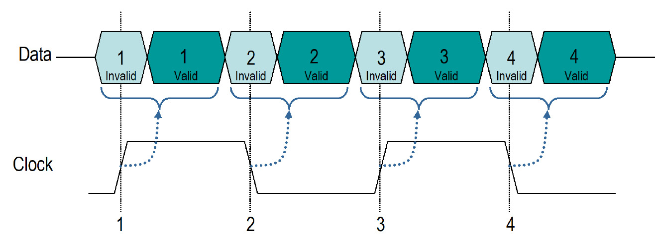
Edge-Aligned Timing Scenario
Edge-aligned timing drives the output clock and data at the same time, aligning the clock with the data invalid window. The start and end of the data valid window are both after the clock edge in time.
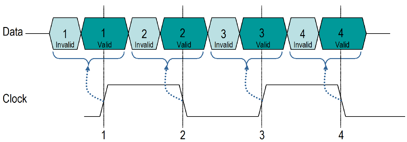
Center-Aligned Timing Scenario
Center-aligned timing aligns the clock with the data valid window at the driving device output. The start of the data valid window is before the clock in time and the end of the data valid window is after the clock in time. This is sometimes referred to as pre-launch of the data signals with respect to the clock output.
Delay Skew
The Parallel Link Designer app timing models specify the start and end of the
data invalid window with respect to the appropriate clock edge. The value of
SKEW_MIN represents the start of the data invalid window and the value
of SKEW_MAX represents the end of the data invalid window. In case of
SKEW_MIN and SKEW_MAX, negative values mean the data
edge is before the clock edge in time, positive values mean the data edge is after the clock
edge in time.

Data Sheet Specifies Data Invalid Window in Center-Aligned Data and Clock
When clock and data are center aligned, and the data sheet specifies the data invalid
window with respect to the clock, you can get the DELAY_SKEW parameters
directly from the data sheet.
Since the start and end of the data invalid window are both before the clock edge in
time, SKEW_MIN and SKEW_MAX are both
negative.
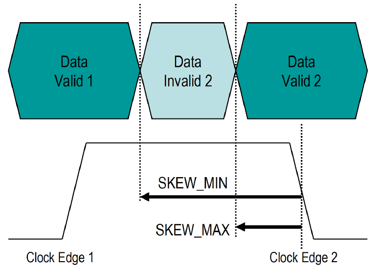
Data Sheet Specifies Data Valid Window in Center-Aligned Data and Clock
When clock and data are center aligned, and the data sheet specifies the data valid
window with respect to the clock, you need to derive the DELAY_SKEW
statement parameters from the data sheet values.

In this case T1 and T2 relate data valid window 2 to clock edge 2. The
DELAY_SKEW statement relates the data invalid window to the clock, so
the SKEW_MIN and SKEW_MAX values that relate data
invalid window 2 to clock edge 2 need to be derived from the data sheet parameters T1, T2
and the bit time (UI) of the data signal.
SKEW_MIN = T2 – BIT_TIME
SKEW_MAX = – T1
This assumes that the parameters T1 and T2 are both positive numbers. Both
SKEW_MIN and SKEW_MAX are negative numbers since
the data invalid window is before the clock in time.
Data Sheet Specifies Data Invalid Window in Edge-Aligned Data and Clock
When clock and data are edge aligned, and the data sheet specifies the data invalid
window with respect to the clock, the DELAY_SKEW parameters can be
taken directly from the data sheet.
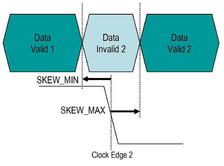
The start of the data invalid window is before the clock edge in time, so
SKEW_MIN is negative. The end of the data invalid window is after the
clock edge in time, so SKEW_MAX is positive.
Data Sheet Specifies Data Valid Window in Edge-Aligned Data and Clock
If clock and data are edge aligned, and the data sheet specifies the data valid window
with respect to the clock, you need to derive the DELAY_SKEW statement
parameters from the data sheet values.
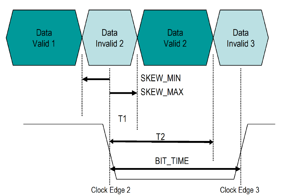
In this case T1 and T2 relate data valid window 2 to clock edge 2. The
DELAY_SKEW statement relates the data invalid window to the clock, so
the SKEW_MIN and SKEW_MAX values that relate data
invalid window 2 to clock edge 2 need to be derived from the data sheet parameters T1, T2
and the bit time (UI) of the data signal.
SKEW_MIN = T2 – BIT_TIME
SKEW_MAX = T1
SKEW_MIN is negative since the start of the data invalid window is
before the clock in time. SKEW_MAX is positive since the end of the
data invalid window is after the clock in time.