Driveline Degrees of Freedom
About Driveline Degrees of Freedom and Constraints
Identifying rotational degrees of freedom (DoFs) is important for building and analyzing a driveline, particularly a complex system with many constraints and external actuations. Simulink® represents driveline DoFs and other Simscape™ system variables as states, among all states of a model, including the pure Simulink states.
This section explains how to identify driveline DoFs, handle constraints, and extract the true or independent DoFs from a complete driveline diagram.
The basic elements of a driveline diagram:
Connection lines
Constraints, including branchings
Dynamic elements
Sensors and sources
Actuating drivelines with motion sources and recording motions with motion sensors
Terminating DoFs
Identify Degrees of Freedom
In a Simscape Driveline™ model, mechanical motions can be rotational or translational: motion around or along one axis. The simplest way to identify a driveline degree of freedom (DoF) is from an angular or linear velocity. A DoF represents a single, distinct angular or linear velocity. Each DoF responds to the torques and forces acting on the inertias and masses making up the driveline. Integrating Newton's equations of motion determines the angular and linear motions. Mechanical DoFs are properties of rotating inertias and translating masses. It is nonetheless consistent and simpler to identify a single Simscape Driveline DoF as a driveline axis with its connected inertias and masses.
To identify and count DoFs in a driveline, look at a Simscape Driveline diagram starting with its mechanical connection lines first, before considering its blocks. Driveline blocks modify the DoFs represented by connection lines by:
Generating torques and forces that act relatively between driveline axes
Adding constraints between driveline axes
Imposing externally actuated torques, forces, and motions
For the basic rules of connection lines and ports, see Build a Drivetrain Model.
Define Fundamental Degrees of Freedom
The basic unit of driveline motion is the DoF represented by an unbroken mechanical connection line. Such lines represent idealized massless and perfectly rigid driveline axes.
Represented by Inertia blocks, rotating bodies with inertias are rigidly attached to and rotate with their axes. Represented by Mass blocks, translating bodies with masses are rigidly attached to and translate along their axes. A single connection line or a set of branched connection lines represents either rotational or translational motion and must be connected to either rotational or translational ports.
Driveline Axes as Fundamental Degrees of Freedom — Mechanical Ports
A connection line anchored by physical network connector ports ![]() represents an idealized driveline axis. The connection line
enforces the constraint that the two connected driveline components rotate or
translate at the same angular or linear velocity, respectively.
represents an idealized driveline axis. The connection line
enforces the constraint that the two connected driveline components rotate or
translate at the same angular or linear velocity, respectively.
![]()
You measure the angular or linear velocity of an axis with an Ideal Rotational Motion Sensor or Ideal Translational Motion Sensor block.
Defining Relative and Absolute Angles and Positions. Relative angle or position is sometimes necessary to compute internally generated torques or forces between pairs of axes (see Define Connected Degrees of Freedom). To determine a relative angle or position, a motion sensor block integrates the relative angular or linear velocity of the pair of axes and adds the result to the initial relative angle or position specified in the block property inspector.
You can define an absolute rotation angle or translation position for a single axis when you measure its motion with a motion sensor, connecting the other physical connection port of the sensor to a Mechanical Rotational Reference or Mechanical Translational Reference. The sensor defines an absolute angle or position by integrating the velocity of the axis and adding the absolute reference angle or position that you provide in the motion sensor property inspector.
Rotating Inertias and Translating Masses Attached to Driveline Axes
You cannot subject a driveline connection line, by itself, to any torques or forces, because it lacks inertia or mass. The other basic element to construct a functioning driveline model is one or more Inertia blocks, one or more Mass blocks, or both. In a real mechanical system, the spinning (or sliding) bodies carry both inertia (or mass) and DoFs.
You attach Inertias and Masses to mechanical connection lines by branching the lines. The attached inertias or masses are subject to whatever torque or force is transmitted by the connection line. The connection line imposes the constraint that everything attached to a single line must be spinning or sliding at the same velocity.

Driveline Axis Branching Rules and Constraints
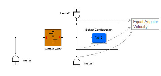
You can branch connection lines. You can connect the end of any branch of a
driveline connection line to a mechanical conserving connection port ![]() only. A set of unbroken, branched connection lines
represents a single DoF.
only. A set of unbroken, branched connection lines
represents a single DoF.
Branched Connection Lines and Angular Velocity Constraints
Define Connected Degrees of Freedom
You can connect two independent driveline axes, representing two independent degrees of freedom (DoFs), by an internal dynamic element. A dynamic element generates a torque or force from the relative angle, position, or motion of the two axes. This torque or force acts between the two axes, which remain independent DoFs, and which transmit the torque or force to their respective attached inertias or masses.
Dynamic Elements — Internal Torque and Force Generation
Apart from gears, most of the Simscape Driveline library blocks are dynamic elements, as are the mechanical rotational and translational blocks of the Simscape Foundation library. These blocks generate internal torques and forces. On a block with two mechanical conserving ports, a single torque or force is applied with positive sign to one axis and negative sign to the other axis. In this figure, torque is applied equally and oppositely to the rod and case axes of the Torsional Spring-Damper.

On blocks with more than two mechanical conserving ports, the total torques or forces flowing in and out of the block still sum to zero, but the torque or force is divided among the ports in a more complex way that depends on the driveline dynamics.
Clutch and Clutch-Like Elements — Conditional Connections
A clutch or clutch-like element is a conditional or dynamic constraint.
If unlocked, a clutch connects two driveline axes and can impose a relative torque between them, leaving the two axes independent. The unlocked clutch is either unengaged, imposing no torque at all; or engaged, imposing kinetic friction as a function of the relative velocity of the two connected axes.
If a clutch locks and applies only static friction between the two connected axes, the two axes are no longer independent. Instead, they act as a single axis, spinning at the same rate. See Define Constrained Degrees of Freedom.
Several other, clutch-like blocks also have locking and unlocking Coulomb friction:
Define Constrained Degrees of Freedom
Certain driveline elements couple driveline axes in a way that eliminates their freedom to move independently. Such elements impose constraints on the motions of the connected axes. A constrained axis is no longer independent of other axes and does not count toward the total net or independent motions of the driveline. Such constraints remove independent degrees of freedom (DoFs) from the system.
Not all constraints are independent. Closing branched connection lines into loops makes some of the constraints within the loops redundant. The number of effective or independent constraints is the number of constraints arising from blocks minus the number of independent closed driveline connection line loops.
Except for clutches and clutch-like elements, driveline constraints are unconditional or static constraints; that is, unchanging over the simulation.
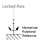
Locking a Driveline Axis
Connecting a driveline connection line to a Mechanical Rotational Reference or Mechanical Translational Reference block freezes the motion of the corresponding driveline axis. It cannot move, and its angular or linear velocity is constrained to be zero during a simulation. Such an axis has no associated independent DoF.
Locking Two Driveline Axes Together with a Clutch or Clutch-Like Element
As long as the conditions for locking are valid, a locked clutch or clutch-like element constrains the two connected driveline axes to spin or slide together. The two axes remain distinct, but only one represents an independent DoF. The other is dependent.
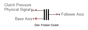
Even if it continues to apply kinetic friction between the axes, an unlocked clutch or clutch-like element no longer imposes a constraint. Instead, it acts as a dynamic element. See Define Connected Degrees of Freedom.
Coupling Driveline Axes with Gears
A gear coupling between two or more driveline axes reduces the independent DoFs of the driveline by imposing constraints. The nature of those constraints depends on the gear that you use. Gear blocks with two connected axes impose one such constraint and reduce the two axes to a single independent DoF.
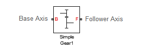
Multiaxis gears impose more than one constraint. For example, a planetary gear imposes two constraints on three axes, reducing the axes to one independent DoF. (This count does not include the fourth, internal DoF, the planetary wheel, which is not connected to an axis with a mechanical port.)

Closed Loops, Effective Constraints, and Constraint Consistency
The actual constraint count to determine the number of DoFs is the number of effective or independent constraints. When connection lines form closed loops, take extra care in counting constraints in a driveline diagram. The presence of closed loops in a diagram reduces the effective constraint count by rendering some of the constraints redundant:
Nconstr = Nbconstr – Nloop
| Nconstr | Number of independent constraints |
| Nbconstr | Number of constraints from blocks |
| Nloop | Number of independent loops |
You can reliably count the number of independent loops by counting the fundamental loops. Fundamental loops have no subloops. You can trace a fundamental loop with only one path. By counting only fundamental loops, you avoid overcounting loops that overlap.
For example, this diagram has two independent loops.
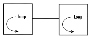
In this diagram, you can draw three loops: two inner loops, left and right, and the outer loop. The outer loop encompasses both inner loops.
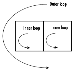
There are two independent loops in this diagram, because only two are fundamental. The outer loop is not fundamental.
Consistency of Constraints. As long as all the velocities constrained by line branch points are equal over the whole loop, a closed loop renders redundant one of the constraints contained within it. (See Driveline Axis Branching Rules and Constraints.) The velocities not directly connected by lines must also be consistent if, for example, they are transferred through gears.
If the velocities along a closed loop cannot be made consistent, the driveline is overconstrained and cannot move.
Actuate, Sense, and Terminate Degrees of Freedom
You can use Simscape
Driveline and related blocks with only one driveline connector port ![]() to originate or terminate a physical connection line.
Terminating a connection line limits the DoF.
to originate or terminate a physical connection line.
Terminating a connection line limits the DoF.
Such blocks include:
Inertia and Mass, which accept torque and force and respond with acceleration.
Mechanical Rotational Reference and Mechanical Translational Reference, which ground DoFs to zero velocity.
Vehicle Body, which implicitly connects the driveline to ground.
These blocks do not have to end a connection line, but can instead be branched off a connection line.
Directionality of Degrees of Freedom
Driveline connection lines have no inherent directionality. The direction of motion and torque flow is determined by the driveline dynamics when you simulate a model.
Effect of Torque and Force Actuation on Degrees of Freedom
Connecting an Ideal Torque Source or Ideal Force Source into a driveline connection line adds the torque or force specified by a physical signal input into that driveline axis. Such an actuation has no effect on the number of system DoFs. The driveline axes transmit torques and forces to their connected Inertias and Masses. The driveline is free to respond to these imposed torques or forces. The motion is simulated by integrating the driveline accelerations (a result of the imposed torques and forces) to obtain the driveline velocities.
Effect of Motion Actuation on Degrees of Freedom
Connecting an Ideal Angular Velocity Source or Ideal Translational Velocity Source to a driveline axis removes the freedom of that axis to respond to torques or forces. Instead, it specifies the axis motion during the simulation from the actuating physical signal input. Unlike torque actuation, motion actuation removes an independent DoF from the system.
For more information about driveline actuation with torques, forces, and motions, see Driveline Actuation.
Count Independent Degrees of Freedom
To determine the number of independent degrees of freedom (DoFs) in your driveline:
Count all the continuous, unbroken driveline connection lines (grouping connected sets of branched lines) in the Simscape Driveline portion of your model diagram. Call the total of such lines NCL.
These lines connect two driveline connector ports or terminate on one mechanical connector port
 . For details, see Define Fundamental Degrees of Freedom and Actuate, Sense, and Terminate Degrees of Freedom.
Count all the constraints arising from blocks that impose constraints on their connected driveline axes. Call the total of such constraints Nbconstr.
Usually, each such block imposes one constraint, but complex gears impose more than one. For details, see Define Constrained Degrees of Freedom.
Count the number of independent loops, Nloop. The effective number of constraints is Nconstr = Nbconstr – Nloop. For details, see Closed Loops, Effective Constraints, and Constraint Consistency.
Count all the motion actuations in your driveline, by counting each motion source block. Call the total of such motion actuations Nmact. For details, see Actuate, Sense, and Terminate Degrees of Freedom.
The number NDoF of independent DoFs in your driveline is:
NDoF = NCL – Nconstr – Nmact = NCL – [Nbconstr – Nloop] – Nmact
A necessary (although not sufficient) condition for driveline motion and successful driveline simulation is that NDoF is positive. Count rotational and translational DoFs separately.
Conditional Degrees of Freedom with Clutches and Clutch-Like Elements
Unlike other driveline components, clutches, and clutch-like elements can undergo a discontinuous state change during a simulation. In general, the number of independent DoFs of a driveline is not constant during its motion. Each state change of one or more clutches changes the independent DoF count. Taken as a whole, different collective states of the clutches of a driveline can have different total net DoFs. To understand a driveline completely, examine each possible collective state of its clutch states to identify its independent DoFs and possibly invalid configurations.
Count Degrees of Freedom in a Simple Driveline with a Clutch
Consider the Two-Speed Transmission example model.
Simple Transmission

This system has five apparent DoFs, represented by these driveline axes:
Branched axis with the Inertia Drive Shaft block
Branched axis with the Inertia Output Shaft block
Axis connecting the high gear clutch block (the clutch for the high clutch schedule) to the Gear High block
Axis connecting the low gear clutch block (the clutch for the low clutch schedule) to Gear Low block
Axis connecting the Clutch Brake block to the Mechanical Rotational Reference block (rotational ground)
There is an apparent closed loop formed by the gear blocks and gear clutch blocks. This loop is real only if both gear clutch blocks are locked.
The actual number of independent DoFs depends on the state of the clutches. The model has no motion sources, so we need consider only gears and clutches as constraints:
The two gears blocks are always acting, therefore yielding two ever-present constraints.
The fifth axis is always connected to the housing (rotational ground).
These three constraints reduce five DoFs to two DoFs.
Now consider the clutches.
Consider first the case where the Clutch Brake block is disabled (free).
If both the high gear clutch and low gear clutch blocks are unlocked, the system has two independent DoFs, one on the left of the gear clutch blocks and the other between the gear clutch blocks and the Clutch Brake block.
If one of these gear clutch blocks is locked, the additional constraint reduces the system to one independent DoF, everything to the left of the Clutch Brake block. (The clutch control schedule is set up to prevent both of these clutch blocks from being locked at the same time.)
If the Clutch Brake block is enabled, the clutch control schedule keeps the two gear clutch blocks disabled.
If the Clutch Brake block is unlocked, the driveline has two independent DoFs: to the left of the gear clutch blocks and between the gear clutch blocks and the Clutch Brake block.
If the Clutch Brake block is locked, the system is reduced to one DoF, to the left of the gear clutch blocks. Everything to the right of the gear clutch blocks is locked to the housing.
This table and abstract diagram summarize the possibilities available in this model.
| Brake Enabling | Clutch Locking | Independent DoFs |
|---|---|---|
| Brake disabled | Both gear clutch blocks unlocked | Two: On the left and on the right of the gear clutch blocks |
| One gear clutch block locked | One: On the left of the Clutch Brake block | |
| Brake enabled | Clutch Brake block unlocked | Two: On the left and on the right of the gear clutch blocks |
| Clutch Brake block locked | One: On the left of the gear clutch blocks |
Degrees of Freedom in the Simple Transmission

Nonphysical Configurations
The clutch schedule design implemented in the Clutch Schedule subsystem excludes nonphysical configurations. It is worth considering them anyway, for the sake of a complete understanding of driveline design. For more information about clutch issues, see Troubleshoot Driveline Modeling and Simulation Issues and Modeling Transmissions.
Both Gear Clutches Locked, Clutch Brake Unlocked. This configuration creates a conflict of DoFs and reduces the independent DoFs to one. The driveline axis to the right of the gear clutch blocks tries to spin at two different rates, as required by two different gear ratios. Two locked clutches enforce two additional constraints on the two remaining DoFs, but form a closed loop, nominally leaving one freedom in the mechanism. Because of the DoF conflict, attempting to simulate such a configuration leads to a Simscape Driveline error.
If the two Gears had identical gear ratios, the DoFs would not conflict, and the simulation would run without error.
One Gear Clutch Locked, Clutch Brake Locked. This configuration also creates a conflict of DoFs and yields zero DoFs. The two locked clutches enforce two additional constraints on the two remaining DoFs and leave no freedom in the mechanism. Driven by the driveline axis to the left, the driveline axis between the gear clutch blocks tries to spin but finds itself locked to the Mechanical Rotational Reference. Attempting to simulate such a configuration leads to a Simscape Driveline error.
Both Gear Clutches Locked, Clutch Brake Locked. This configuration is also overconstrained. Three locked clutches enforce two effective constraints on the remaining two DoFs (after taking into account the closed loop) and yield NDoF = 0. In addition, the driveline axis to the right of the gear clutch blocks tries to spin at two different nonzero rates, while remaining locked to the Mechanical Rotational Reference, creating two distinct DoF conflicts.