CCSDS Optical High Data Rate Waveform Generation for 1550nm
This example shows how to generate a high data rate (HDR) waveform for a 1550 nm carrier wavelength in free-space optical communication systems. The example describes the functions of the channel coding and synchronization sublayer and physical layer, as defined in Consultative Committee for Space Data Systems (CCSDS) 141.10-O-1 sections 3 and 4 [1]. In this example, HDR optical communications aim to support various near-Earth optical communication link applications by using wavelengths in the 1550 nm range, where a high data rate is the primary consideration in the link design. These links operate at rates of approximately 100 Gb/s, enabling large data transfers within short contact times.
This figure shows the coding and synchronization sublayer of the data link layer and the physical layer at the transmitting end. The coding and synchronization sublayer receives input frames from the data link protocol sublayer, performs the synchronization and channel coding functions, and delivers a binary vector to the physical layer. The physical layer then takes the binary vector, which contains pseudo-randomized frames from the coding and synchronization layer, and generates modulated samples using phase, intensity, and burst modulation.

Set Configuration Parameters
Specify the configuration parameters for the coding and synchronization sublayer in the cfgParams structure. The input to the coding and synchronization sublayer is a sequence of fixed-length or variable-length frames. To generate synchronization marked frames (SMFs), either use the attach synchronization marker (ASM) method or the generic frame procedure (GFP) method, as specified in CCSDS 141.10-O-1 section 3.3 [1]. Use the ASM method for fixed-length input frames and the GFP method for variable-length input frames.
cfgParams.SMFGenerationMethod ="ASM"; if cfgParams.SMFGenerationMethod == "GFP" % In GFP mode, NumBytesInFrame can be a vector indicating input data of % variable length frames. This example considers 3 frames with % different lengths. cfgParams.NumBytesInFrame = [5078 4503 9111]; cfgParams.GFPMode =
"short"; if cfgParams.GFPMode == "full" % 8-bit vector indicating CCSDS transfer frames as specified in [1] % section 3.3.3.3.3. For other values, refer to [2] section % 6.1.2.1.1.4. cfgParams.GFPUserPayloadID = [1 1 1 1 0 0 0 0]'; cfgParams.GFPExtensionType =
"null"; if cfgParams.GFPExtensionType == "linear" % 8-bit vector indicating ID for the communication channel cfgParams.GFPChannelID = [0 0 0 0 0 0 0 1]'; end end else % cfgParams.SMFGenerationMethod = "ASM" % In ASM mode, NumBytesInFrame is a scalar indicating input data % frames of fixed length. This example considers fixed frames each 1504 % bytes in size. cfgParams.NumBytesInFrame = 1504; end cfgParams.FECCode =
"RS"; if strcmp(cfgParams.FECCode,"BCH-LDPC") cfgParams.LDPCCodeRate =
"1/4"; end % Set the channel interleaver parameters cfgParams.SymbolSize =
8; % cfgParams.NumRows must be a factor of 64800/cfgParams.SymbolSize cfgParams.NumRows = 9; % cfgParams.NumRows*cfgParams.RegisterLengthIncrement must be a multiple of % 64800/cfgParams.SymbolSize cfgParams.RegisterLengthIncrement = 900; % Set a 288-bit unique word content ID and 22-bit physical layer control message cfgParams.UniqueWordID = int2bit([1e14, 23e13, 145e12, 89e13, 1.3e14, 146e12]',48); cfgParams.PLControlMessage = zeros(22,1);
Specify the configuration parameters for the physical layer in the cfgParams structure.
cfgParams.PhaseModulation ="DPSK"; cfgParams.IntensityModulation =
"RZ50"; cfgParams.SlotRate =
10e9; cfgParams.SampleRate = 200e9; % Set SampleRate as an integer multiple of SlotRate cfgParams.BurstParameter =
0;
Coding and Synchronization Sublayer
This figure shows the functions performed by the coding and synchronization sublayer at the transmitting end.

Generate the input data to the coding and synchronization layer based on the SMFGenerationMethod field in the cfgParams structure.
% Generate input frames with random data
rng("default")

if cfgParams.SMFGenerationMethod == "ASM"
    % Generate fixed length data consisting of 3 frames, each 1504 bytes in
    % size.
    numFrames = 3;
    data = randi([0 1],cfgParams.NumBytesInFrame*8,numFrames);
else % cfgParams.SMFGenerationMethod = "GFP"
    % Generate data consisting of a cell array containing 3 frames with
    % variable lengths.
    data = {randi([0 1],cfgParams.NumBytesInFrame(1)*8,1);
        randi([0 1],cfgParams.NumBytesInFrame(2)*8,1); randi([0 1],cfgParams.NumBytesInFrame(3)*8,1)};
end
ASM
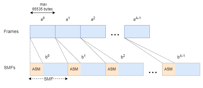
In the ASM method, the input consists of a sequence of fixed-length transfer frames. In this method, you prepend a 32-bit ASM in hexadecimal format, 1ACFFC1D, to each transfer frame. This figure shows the construction of SMFs using the ASM method.
Short GFP
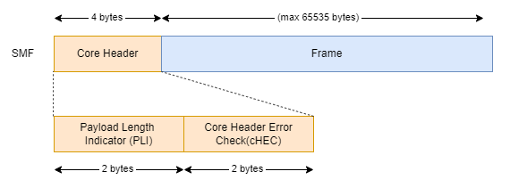
This figure shows the construction of SMFs using the short GFP method. In the short GFP method, you prepend 32-bit core header to each input frame. The core header consists of a 16-bit payload length indicator (PLI) field and a 16-bit core header error check (cHEC) field. The PLI field represents the number of bytes in each input frame. To generate the core header, calculate the cyclic redundancy check (CRC) sequence cHEC over the PLI field, as specified in ITU-T G.7041/Y.1303 section 6.1.1.2.1 [2]. Then, scramble the core header and the input frame to create the SMFs.
Full GFP
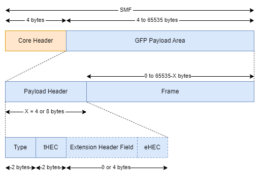
This figure shows the construction of SMFs using the full GFP method. In the full GFP method, you prepend a 32-bit core header to each GFP payload area. Generate the core header similarly to the short GFP method, except the PLI field in the core header now represents the number of bytes in each GFP payload area.
Prepend a payload header to the input frame to generate the GFP payload area. The maximum input frame length is , where represents the length of the payload header. The length of the payload header depends on the value of the GFPExtensionType field in the cfgParams structure.
When
GFPExtensionTypeis set to "null", the payload header contains only the type field and the type header error check (tHEC) field.When
GFPExtensionTypeis set to "linear", the payload header additionally contains the extension header field and the extension header error check (eHEC) field, appended to the type and tHEC fields respectively.
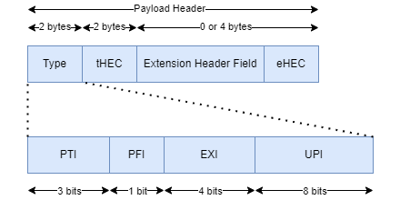
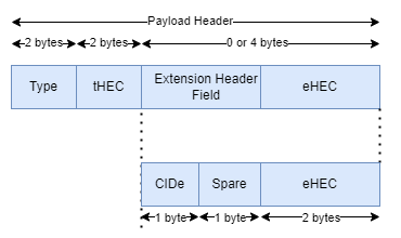
This figure shows the construction of the Type field, a 16-bit binary vector containing these attributes:
Payload type identifier (PTI) — Set to
[0 0 0]for client data frames, as specified in ITU-T G.7041/Y.1303 table 6-1 [2].Payload frame check sequence indicator (PFI) — Set to
0,as the payload frame check sequence (pFCS) field is not used, as specified in CCSDS 141.10-O-1 section 3.3.3.3.2 [1].Extension header identifier (EXI) — A 4-bit binary vector whose value depends on the value of the
GFPExtensionTypefield in thecfgParamsstructure.User payload identifier (UPI) — An 8-bit vector specifying the type of payload information present in the input frames, as specified in ITU-T G.7041/Y.1303 table 6-3 [2]. In this example, for input CCSDS frames, the UPI is set to
[1; 1; 1; 1; 0; 0; 0; 0].
This table shows the value of EXI and the usage for each GFP extension type.
EXI Value |
| Usage |
[0 0 0 0] | " | Extension header applicable for logical point-to-point configuration, where the transport path is dedicated to one client signal. |
[0 0 0 1] | " | Extension header applicable for scenarios where several independent links aggregate onto a single transport path. |
For a linear GFP extension type, the extension header field consists of an 8-bit channel identifier (CID), indicating one of the 256 communication channels at a GFP termination point, and a spare field. The eHEC field is the CRC sequence calculated over the extension header field using the same method as the cHEC.
Scramble the GFP payload area and the core header to generate SMFs.
% Generate synchronized marked frames from data frames
SMF = HelperCCSDSHDRSMFGenerator(data,cfgParams);
if isempty(SMF)
    hdrWaveform = zeros(0,1);
    return;
end
Slicer
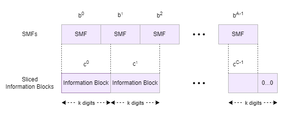
Slice the sequence of SMFs into information blocks of length k. If the size of the last information block is less than k, then the slicer fills that block with the minimum number of 0s required to increase the block size to a multiple of k. For Reed Solomon (RS) encoding, k is set to 60160. For Bose-Chaudhuri-Hocquenghem (BCH) + Low-Density Parity-Check (LDPC) channel encoding, k is determined based on the value of the LDPCCodeRate field in the cfgParams structure. This table shows the relationship between the LDPCCodeRate value and the information block size (k), as specified in CCSDS 141.10-O-1 table 3-1.
LDPC Code Rate | Information Block Size ( |
1/4 | 15976 |
1/3 | 21376 |
2/5 | 25696 |
1/2 | 32176 |
3/5 | 38656 |
2/3 | 43008 |
3/4 | 48376 |
4/5 | 51616 |
5/6 | 53808 |
8/9 | 57440 |
9/10 | 58160 |
This figure shows the construction of information blocks from the SMFs.
Generate information blocks from the SMFs.
% Slice SMFs into information blocks
if strcmp(cfgParams.FECCode,"BCH-LDPC")
    coderateRef = {'1/4','1/3','2/5','1/2','3/5','2/3','3/4','4/5','5/6','8/9','9/10'};
    infoSizeRef = [15976 21376 25696 32176 38656 43008 48376 51616 53808 57440 58160];
    infoBlockSize = infoSizeRef(strcmp(coderateRef,cfgParams.LDPCCodeRate));
else
    infoBlockSize = 60160;
end

if iscell(SMF)
    SMFVector = vertcat(SMF{:});
else
    SMFVector = SMF(:);
end
slicerOut = buffer(SMFVector,infoBlockSize);
CRC attachment
Append 32 CRC bits to the end of each information block, as specified in CCSDS 141.10-O-1 section 3.5 [1].
% Generate CRC
CRCLen = 32;
numInfoBlocks = size(slicerOut,2);
crcOutLen = infoBlockSize + CRCLen;
crc32Config = crcConfig(Polynomial="x^32+x^29+x^18+x^14+x^3+1", ...
    InitialConditions=1,DirectMethod=true);
crcOut = crcGenerate(logical(slicerOut),crc32Config);
Forward Error Correction (FEC)
Encode the CRC-generated information blocks using either Digital Video Broadcast Second Generation (DVB-S2) BCH + LDPC encoding, as specified in section 5.3 of [3], or CCSDS RS encoding, as specified in section 4 of [4]. The choice of FEC method depends on the value of the FECCode field in the cfgParams structure. Both encoding methods yield FEC output frames, each consisting of 64800 bits.
Channel Interleaver
Interleave the FEC-encoded frames through a convolutional interleaver as symbols. The number of bits per interleaver symbol is determined by the value of the SymbolSize field in the cfgParams structure. The interleaver consists of rows, where each row contains a shift register of length , consisting of interleaver symbols. The interleaver de-multiplexes the input interleaver binary digits in groups of SymbolSize bits into the rows. The interleaver then multiplexes the outputs of the shift registers in groups of SymbolSize bits. Choose the values of and such that is a multiple of , which itself is a multiple of . After processing the last symbol, the interleaver continues operating for an additional steps before the last symbol appears at the output. Thus, the output contains more symbols than the input. The values of and are determined using the values of the NumRows and RegisterLengthIncrement fields in the cfgParams structure, respectively.
% Initialize parameters for RS encoding as specified in [1] section 3.6.3
J = 8;                   % Bits per RS symbol
E = 8;                   % Error correcting bits
I = 36;                  % Interleaving depth
n = 2^J - 1;             % Symbols per RS codeword
k = n-2*E;               % Message length
RSLen = crcOutLen/(I*8); % Shortened message length

if strcmp(cfgParams.FECCode,"BCH-LDPC")
    % Initialize parameters for LDPC encoding
    parityMatrix = dvbsLDPCPCM(cfgParams.LDPCCodeRate);
    ldpcCfg = ldpcEncoderConfig(parityMatrix);
end

% Initialize parameters for Convolutional interleaver

FECLen = 64800;                        % In bits
S = FECLen/cfgParams.SymbolSize;
N = cfgParams.NumRows;
B = cfgParams.RegisterLengthIncrement;
M = 2^cfgParams.SymbolSize;

if mod(N*B,S) ~= 0
    error("NumRows*RegisterLengthIncrement must " + ...
        "be a multiple of 64800/SymbolSize")
elseif mod(S,N) ~= 0
    error("64800/SymbolSize must be a multiple of NumRows")
end

% Set random number generator to avoid generating different initial states
% each time
rng(1, "twister")
reqInitStates = randi([0 M-1],S,N*(N-1)*B/S);
convIntrlvrObj = comm.ConvolutionalInterleaver(NumRegisters=N, ...
    RegisterLengthStep=B);

for i = 1:size(reqInitStates,2)
    currIn = reqInitStates(:,i);
    convIntrlvrObj(currIn(1:S));
end

% Generate random additional symbols required for the last symbol to appear at the output
addSymTemp = randi([0 M-1],N*B*(N-1),1);
% Reshape into blocks of length S, as comm.ConvolutionInterleaver restricts
% input size change
additionalSym = reshape(addSymTemp,S,[]);
% Number of additional blocks generated after channel interleaving
addOutBlocks = size(additionalSym,2);
chSymOut = zeros(S,numInfoBlocks+addOutBlocks);
for blockIdx = 1:numInfoBlocks
    if strcmp(cfgParams.FECCode,"BCH-LDPC")
        % BCH encoding
        bchOut = HelperCCSDSHDRBCHEncode(crcOut(:,blockIdx));
        % LDPC encoding
        FECOut = ldpcEncode(logical(bchOut),ldpcCfg);
    else
        % CCSDS RS encoding
        FECOut = ccsdsRSEncode(crcOut(:,blockIdx),k,I,RSLen);
    end

    % Channel interleaving
    bitIn = reshape(FECOut,cfgParams.SymbolSize,[]);
    symIn = bit2int(bitIn,cfgParams.SymbolSize)';
    chSymOut(:,blockIdx) = convIntrlvrObj(symIn);
end

% Pass the additional blocks through the channel interleaver for the last
% symbol to appear at the output
for blockIdx = 1:addOutBlocks
    chSymOut(:,blockIdx+numInfoBlocks) = convIntrlvrObj(additionalSym(:,blockIdx));
end

% Convert back the interleaver symbols to bits
chBitOut = int2bit(chSymOut(:),cfgParams.SymbolSize);
Physical Layer Framing
This figure shows the construction of the physical layer frame.
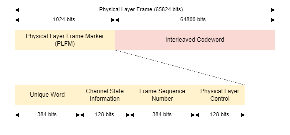
Prepend a 1024-bit physical layer frame marker (PLFM) to each interleaved codeword to create a physical layer frame. The PLFM consists of:
Unique word — A 384-bit vector that helps in achieving codeword synchronization, channel state estimation, and identifying the content of frame data. The first 96 bits are represented in hexadecimal notation as
EBE2587B22EE5319A15AA382, while the subsequent 288 bits are mission-specific, determined by theUniqueWordIDfield in thecfgParamsstructure. ThisUniqueWordIDspecifies the essential link information, like the source and destination or the modulation and coding.Channel state information — A 128-bit field that provides information for decoding the frame contents in multi-hop link scenarios. Correlate the received unique word field with the correct unique word to provide an estimate of the channel quality. These correlation values are then mapped to 4-bit channel state values, as specified in CCSDS 141.10-O-1 table 3-3 [1]. In this example for the single-hop link, the channel state sequence is set to
[1 1 1 1 0 0 0 0]'.Frame sequence number — The 22-bit frame sequence number represents the frame sequence number field incremented with each transmitted frame at the data source for a particular unique word. The frame sequence number helps identify dropped frames in a multi-hop link scenario. The 384 binary digits in the frame sequence number are generated by BCH-encoding the 22-bit frame sequence number as specified in CCSDS 141.10-O-1 section 3.9.5 [1].
Physical layer control field — The 128 binary digits transports messages with acknowledgments to support end-to-end feedback loops involving the cooperation of both terminals. The 22-bit
PLControlMessagefield of thecfgParamsstructure specifies the physical layer control message value. Generate the 128-bit physical layer control field by BCH-encoding the 22-bit physical layer control message as specified in CCSDS 141.10-O-1 section 3.9.6 [1].
Pseudo-Randomization
Pseudo-randomize the physical layer frame to generate the binary vector to transmit to the physical layer as specified in CCSDS 141.10-O-1 section 3.10.1 [1].
% Physical layer framing
PLFrameLen = 1024;               % In bits
cssInLen = 8;                    % In bits
numCW = length(chBitOut)/FECLen;

interleavedCW = reshape(chBitOut,FECLen,numCW);
genPolyCSS = bchgenpoly(127,cssInLen,"D7 + D3 + 1","double");
fsnInLen = 22;
genPolyFSN = bchgenpoly(127,fsnInLen,"D7 + D3 + 1","double");
bchCSS = crcConfig("Polynomial",genPolyCSS);
bchFSN = crcConfig("Polynomial",genPolyFSN);
% Channel state sequence for first hop as specified in [1] section
% 3.9.4.3
channelStateSeq = [1 1 1 1 0 0 0 0]';
% Generate Pseudo-random sequence
pnLen = 65440;
pnSeqObj = comm.PNSequence("SamplesPerFrame",pnLen, ...
    Polynomial="z^16 + z^15 + z^13 + z^4 + 1", ...
    InitialConditions=ones(16,1));
pnSequence = pnSeqObj();
sysSeqLen = 384;
txOut = zeros((FECLen+PLFrameLen),numCW);
% Frame alignment sequence 0XEBE2587B22EE5319A15AA382
FAS = int2bit(hex2dec(["EBE258","7B22EE","5319A1","5AA382"]'),24);

for cwIdx = 1:numCW
    uniqueWord = [FAS; cfgParams.UniqueWordID];
    % BCH encode the channel state sequence to generate channel state
    % information
    CSSbchOut = crcGenerate(channelStateSeq,bchCSS);
    CSI = [0; CSSbchOut(cssInLen+1:end); channelStateSeq];

    % Generate frame sequence number field
    frameSeq = int2bit(cwIdx,22);
    FSNbchOut = crcGenerate(frameSeq,bchFSN);
    temp = [0; FSNbchOut(fsnInLen+1:end); frameSeq];
    FSN = repmat(temp,3,1);

    % Generate physical layer control field
    PLCFbchOut = crcGenerate(cfgParams.PLControlMessage,bchFSN);
    PLCF = [0; PLCFbchOut(fsnInLen+1:end); cfgParams.PLControlMessage];

    % Physical layer frame marker - [Uniqueword (384 bits), Channel state
    % information (128 bits), Frame sequence number (384 bits), physical layer
    % control (128 bits)]
    PLFM = [uniqueWord; CSI; FSN; PLCF];
    PLF = [PLFM;interleavedCW(:,cwIdx)];

    % Pseudo-randomize the physical layer frame
    txOut(1:sysSeqLen,cwIdx) = PLF(1:sysSeqLen);
    txOut(sysSeqLen+1:sysSeqLen+pnLen,cwIdx) = xor(PLF(sysSeqLen+1:end),pnSequence);
end
Physical Layer
This figure shows the functions performed by the physical layer at the transmitting end.

Modulate the pseudo-randomized physical layer frames from the coding and synchronization sublayer in each transmission slot using a combination of phase and intensity modulation. Then transmit the modulated data as bursts based on the value of the BurstParameter field in the cfgParams structure.
% Perform phase modulation
switch cfgParams.PhaseModulation
    case "DPSK"
        phaseOut = dpskmod(txOut(:),2);
    case "DQPSK"
        % Rearrange the input to support custom symbol mapping
        flippedTxOut = fliplr(reshape(txOut(:),2,numel(txOut)/2).').';
        flippedSym = bit2int(flippedTxOut(:),2);
        phaseOut = dpskmod(flippedSym,4,0,"gray");
    case "BPSK"
        phaseOut = pskmod(txOut(:),2);
    case "QPSK"
        phaseOut = pskmod(txOut(:),4,pi/4,[0 2 3 1],InputType="Bit");
end

% Perform intensity modulation
intensityOut = HelperCCSDSHDRIntensityModulation(phaseOut, ...
    cfgParams.IntensityModulation,cfgParams.SlotRate, ...
    cfgParams.SampleRate);

% Perform burst modulation
sps = ceil(cfgParams.SampleRate/cfgParams.SlotRate);
hdrWaveform = burstModulation(intensityOut,cfgParams.BurstParameter, ...
    cfgParams.PhaseModulation,sps);

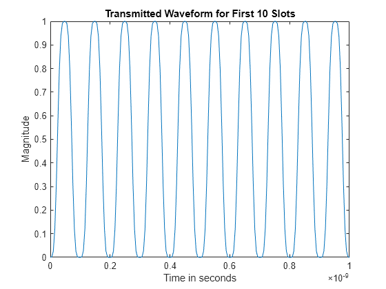
% Plot CCSDS HDR physical layer output for the first 10 slots
numSlots = 10;
x = hdrWaveform(1:numSlots*sps,1);
t = linspace(0,numSlots/cfgParams.SlotRate,numSlots*sps);
plot(t,abs(x(:)))
xlabel("Time in seconds")
ylabel("Magnitude")
title("Transmitted Waveform for First " + numSlots + " Slots")
% Display the frequency spectrum of the generated CCSDS optical HDR waveform.
rxAnalyzer = spectrumAnalyzer(SampleRate=cfgParams.SampleRate,AveragingMethod="exponential");
rxAnalyzer(hdrWaveform(:))

Supporting Files
The example uses these helper files.
HelperCCSDSHDRSMFGenerator— Generate synchronization marked frames.HelperCCSDSHDRBCHEncode— Perform BCH encoding.HelperCCSDSHDRIntensityModulation— Perform intensity modulation.
References
[1] The Consultative Committee for Space Data Systems. Optical High Data Rate (HDR) Communication-1550nm, Experimental Specification, Issue 1. CCSDS 141.10-O-1. Washington, D.C.: CCSDS, June 2022.
[2] Generic Framing Procedure. ITU-T G.7041/Y.1303. Geneva: ITU, 2016.
[3] ETSI Standard EN 302 307-1 V1.4.1(2014-11). Digital Video Broadcasting (DVB); Second Generation Framing Structure, Channel Coding and Modulation Systems for Broadcasting, Interactive Services, News Gathering and other Broadband Satellite Applications (DVB-S2).
[4] TM Synchronization and Channel Coding. Recommendation for Space Data System Standards. CCSDS 131.0-B-4. Washington, D.C.: CCSDS, April 2022.
Local Function
burstModulation — Performs burst modulation as specified in CCSDS 141.10-O-1 section 4.4.4 [1].
function burstOut = burstModulation(in,D,phaseFormat,sps)
%   BURSTOUT = burstModulation(IN,D,PHASEFORMAT,SPS) performs burst
%   modulation to the data in IN, as specified in CCSDS 141.10-O-1 section
%   4.4.4. D is the burst parameter and must be 0, 1, 3, 7, 23, or 29.
%   PHASEFORMAT is a string scalar or character vector representing the
%   type of phase modulation, and must be "BPSK", "QPSK", "DPSK", or
%   "DQPSK". SPS is a positive integer representing samples per slot. The
%   output, BURSTOUT, is a column vector representing burst-modulated data.

burstLen = 176;
burstSamplesLen = sps*burstLen;
if D == 0
    burstOut = in(:);
else
    burstIn = reshape(in, burstSamplesLen, []);
    burstInLen = size(burstIn,2);
    burstOutLen = burstInLen*(1 + D);
    burstOut = zeros(burstSamplesLen,burstOutLen);
    burstOut(:,1:D+1:burstOutLen) = burstIn;

    if strcmp(phaseFormat,"DPSK") || strcmp(phaseFormat,"DQPSK")
        burstOut(end-sps+1:end,D+1:D+1:burstOutLen) = burstIn(end-sps+1:end,:);
    end
end
end