Optical Wireless Communications
Optical wireless communications (OWC) is an optical communication technology that provides superior bandwidth capabilities and high-speed data transmission. OWC wirelessly transmits data using light waves across the infrared (IR), visible, and ultraviolet (UV) spectra. The system modulates the light signals, which then traverse through free space to reach the receiver, which demodulates them. OWC offers a solution to the growing demand for high-speed data transmission by providing extremely high speeds, enhanced security, and reduced interference. These properties make OWC ideal for environments that require high bandwidth and secure communication, such as low Earth orbiting intersatellite links. You can widely deploy OWC in a variety of scenarios, from urban areas that need secure and cost effective data transfer to deep space missions. The data transmitted over free space can achieve speeds of up to 200 gigabits per second (Gbps) [8]. This page explores the core components, functionalities, and working principles of the primary classifications of OWC: free space optical communication (FSOC) and deep space optical communication (DSOC).
OWC systems achieve high data rates and are power efficient compared to RF systems, typically operating at power levels around 1–10 watts, whereas RF transmitters often require 100–1000 watts to achieve similar data rates. This enhances the speed and efficiency of transmitting gigabytes of data, such as high-resolution images and videos. OWC offers high gain with narrow beam divergence of radiation, and have a has modulation bandwidth, significantly increasing the information-carrying capacity. The usable bandwidth at an optical frequency is in the order of THz, almost 103 times that of a typical RF carrier. OWC systems operate in an unlicensed spectrum, reducing initial setup costs and development time. This boosts communication efficiency, reliability, and cost-effectiveness, paving the way for more ambitious space missions. OWC provides more secure communication channel than an RF system due to its narrow light beam, which is challenging to intercept or tap into, significantly reducing the risk of eavesdropping. OWC benefits from the flexibility of wireless data transmission through free space, as opposed to fiber optic communications (FOC), which relies on cables.
This figure illustrates a universal global wireless optical network and its applications in different environments. The figure depicts space-based links between satellites and spacecraft in orange and ground-based connections between base stations, ground stations, and vehicles in black. All the links are bidirectional.

The atmosphere of the Earth causes degradation in OWC systems, such as clouds, turbulence, and aerosols that absorb signals or cause them to fade. To counter atmospheric degradation, OWC systems employ various techniques, such as using wavelength diversity to reduce the impact of atmospheric absorption. The more geographically scattered the ground stations are in different regions of the Earth, the higher the chances of maintaining a clear field of line-of-sight (LOS) to the spacecraft for sustained data transmission. OWC systems leverage real-time weather data to predict atmospheric conditions that could impact signal quality. By integrating this real-time data, they can dynamically adjust transmission parameters, such as beam direction and power, to mitigate interference and maintain a stable communication link. OWC systems also face challenges such as pointing accuracy and susceptibility to cloud cover, which can disrupt communication links. Pointing, acquisition, and tracking (PAT) are important for maintaining alignment between the transmitter and receiver, and any misalignment can significantly degrade the communication link.
Operating Bands
OWC transmits signals using free space as a medium, and maintains unguided visible, IR, and UV light within the wavelength spectrum.
UV spectrum — The wavelength range for UV light is from 10 nm to 400 nm (30 PHz to 750 THz). Due to its shorter wavelength and greater energy compared to other light, UV transmits signals more effectively over greater distances. The UV spectrum is often used in secure communication applications due to its low scattering and absorption properties in non-LOS environments.
Visible spectrum of light — The wavelength range for visible light is from 380 nm to 750 nm (790 THz to 400 THz). This range is preferred for short-range applications. In various applications, such as wireless local area networks (WLAN) [10], wireless personal area networks (WPAN) [11], and vehicular networks, visible light communication (VLC) uses visible light to transmit data over short distances.
IR spectrum — The wavelength range for IR light is from 750 nm to 1 mm (430 THz to 300 GHz). The IR spectrum is used in medical applications, remote sensing, and IR spectroscopy. Because not all wavelengths of the IR spectrum are safe for human eyes, you must select wavelengths that minimize the risk in situations where human exposure is possible.
FOC operates from 850 nm to 1550 nm, making its equipment readily reusable for FSOC and DSOC systems. FSOC and DSOC make heavy use of the 850 nm, 1064 nm, and 1550 nm wavelengths of the spectrum. FSOC systems usually use IR light for point-to-point terrestrial communication over short to medium range.
Free Space Optical Communications (FSOC)
FSOC systems use pulses of light wirelessly transmit data through open space, enabling high-speed communication over various distances. These systems are used in inter-satellite links, satellite-to-ground communications, ground-to-satellite communications, and terrestrial communications, and are more effective for short to medium distances. The FSOC technique uses lenses or parabolic mirrors to limit and redirect a beam of light toward the receiver. Upon arrival at the receiver, a lens or mirror captures the laser light and focuses it onto an optical sensor such as a photodetector, which then outputs electrical signals for further processing. The operating band for FSOC is between 780 nm and 1600 nm in wavelength, which corresponds to a frequency range from approximately 187.5 THz to 384 THz. FSOC systems typically use three specific wavelengths: 850 nm, 1064 nm, and a wavelength in the range from 1310 nm to 1550 nm.
FSOC eliminates the need for cables, reducing infrastructure and installation costs, and is ideal for urban areas or places where laying cables is impractical. However, obstructions or dynamic environments can lead to signal degradation.
FSOC is classified into three categories: terrestrial, space-based, and space-to-ground/ground-to-space.
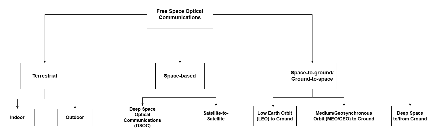
Terrestrial — Terrestrial focuses on Earth-related uses, which consists of indoor and outdoor communication systems. Short-range in-building FSOC data transfer is one of the most common applications of indoor FSOC systems. Some key applications include high-speed wireless networks for secure data centers, including communication within multiple server racks and in-building communications [9].
Space-based — FSOC includes two types of space-based communications: satellite-to-satellite communications and DSOC. Satellite-to-satellite systems operate above the atmosphere of the Earth, thus avoiding interference from tropospheric and ionospheric effects. DSOC involves both space-to-space and ground-to-space communications, dealing with atmospheric effects when applicable.
Space-to-ground and ground-to-space — These communications face atmospheric interference, and are categorized by satellite altitude. LEO satellites are primarily used for fast data transfer, such as internet services and Earth imaging. Medium Earth orbit (MEO) satellites support navigation systems such as GPS, a space-based radio-navigation infrastructure that uses a constellation of satellites to provide accurate positioning and timing. Geostationary orbit (GEO) satellites remain over a specific location, aiding in TV broadcasts and weather monitoring. DSOC manages long-distance interactions with missions many light-years from Earth, requiring advanced techniques to handle signal delays.
Working Principle
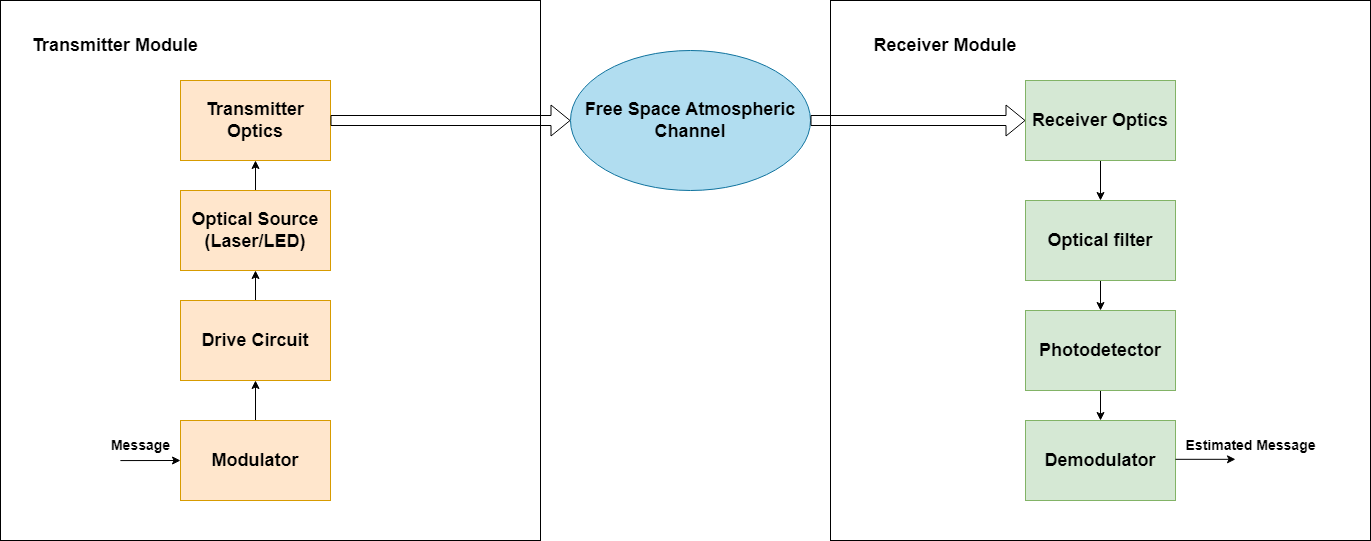
An FSOC system consists of three subsystems: a transmitter module, a free space atmospheric channel, and a receiver module. The working principle of FSOC involves converting electrical signals into optical signals, transmitting them through the atmosphere using lasers or light emitting diode (LED) sources, and then reconverting them back into electrical signals at the receiver.
The subsequent sections provide detailed explanations of the transmitter module, FSOC modulation schemes, free space atmospheric channel, types of detector, receiver module, and PAT technique.
Transmitter Module
The FSOC transmitter module initiates communication through signal processing and optical components. The input message consists of the information to transmit, which can be in either a digital or analog data format. The modulator receives the message and processes the input signal for optical transmission. The modulator sends the signal to the drive circuit, which provides control and stabilization of the optical source output radiation against temperature variations to ensure signal quality and reliability. The drive circuit then powers the optical source using either a laser diode or an LED. Typically, a laser diode is preferable as it produces coherent, high-intensity light beams. The optical source transmits the light to the transmitter optics, where collimators and telescopes gather and collimate the light beam. A collimator is an optical device that aligns and focuses the light into a parallel beam.
Modulation Techniques
Some of the widely used modulation techniques in satellite-based FSOC include:
Pulse position modulation (PPM) — In PPM, data is encoded by varying the position of a single pulse within a predetermined time slot to represent different data values. This modulation scheme is power-efficient because it consumes much less power to transmit data as compared to others. Thus, this scheme is suited to energy-constrained systems like deep space communications. However, PPM requires more bandwidth than other modulation techniques, such as on-off keying (OOK) or pulse amplitude modulation (PAM).
On-off keying non-return-to-zero (OOK-NRZ) modulation — In OOK-NRZ, data is represented by the presence or absence of a light pulse. This modulation technique is simple and cost-effective, making it suitable for short to medium-range satellite communications. However, it is less power-efficient compared to PPM, and can be more susceptible to noise and interference.
Free Space Atmospheric Channel
The FSOC signal must pass through the atmosphere, and by the time it reaches the receiver, it degrades in quality due to several factors.
Absorption happens when atmospheric components like water vapor, dust, and aerosols absorb parts of the FSOC signal. This results in energy loss, reducing the strength of the signal as it travels through the atmosphere. The absorbed energy is converted into other forms, such as heat, which further diminishes the signal power.
For an example, see Optical Satellite Communication Link Budget Analysis. This example analyzes the link budget for optical communication, highlighting atmospheric effects like absorption and scattering on uplink and downlink signals.
Scattering occurs when particles such as water vapor, dust, and aerosols in the atmosphere interact with the FSOC signal. This interaction changes the distribution of the signal, causing distortion or weakening. Scattering can lead to energy loss and diminished signal strength, making it harder for the signal to reach its intended destination with full power.
Turbulence in the atmosphere is primarily caused by uneven air conditions resulting from variations in temperature and pressure. This turbulence leads to random changes in the FSOC signal, a phenomenon known as scintillation, which causes fluctuations in signal strength. As the optical beam travels through turbulent air, its direction and spread can be altered, reducing the total power received at the destination. There are some of the channel models that model turbulence: log normal distribution, negative exponential distribution, and gamma distribution.
Receiver Module
The receiver module processes the captured light from the optical signal to recover the transmitted data. This process starts with the receiver optics, which act like a form of telescope, collecting and focusing on the incoming light beam from an external source. Once the signal has been extracted, the light passes through an optical filter that serves two key functions. First, it filters out unwanted background radiation and ambient light that degrades the signal and could prevent it from reaching its destination, and then it isolates the specific wavelength for the transmitted signal. This process improves the signal-to-noise ratio of the overall system. This stage is important for maintaining communication quality, especially under varied atmospheric conditions.
The system then sends the filtered optical signal to the photodetector, a semiconductor photodiode, which converts the optical signal into an electrical signal. The photodetector must be small because a larger photodetector takes longer to respond. Depending on the desired system sensitivity, the system uses either a standard photodiode or an APD. Next, the demodulator processes the detected signal to remove channel distortions and recover the original data from the modulated signal. For an example of how to measure the block error rate (BER) in a Consultative Committee for Space Data Systems (CCSDS) high photon efficiency (HPE) telemetry (TM) end-to-end optical link, see CCSDS High Photon Efficiency Telemetry Optical Link Simulation.
Pointing, Acquisition, and Tracking (PAT)
In FSOC systems, the PAT mechanism is necessary in terrestrial and satellite communication to establish stable and reliable communication links. PAT operation correctly aligns and maintains the optical beam between the transmitting and receiving nodes with high precision.
This figure illustrates the PAT process in an FSOC system, used for CCSDS high data rate (HDR) links and in Space Development Agency (SDA) specifications. The goal of PAT process is to establish a stable optical link between a central terminal (C), which is a transmitter, and a peripheral terminal (P), which is a receiver. Proper PAT ensures the establishment of a stable link, which is essential for high-quality data transmission. Initially, both the transmitter and receiver may have pointing errors due to misalignment. If these errors occur, they can lead to signal loss because of the extremely narrow beamwidth of the optical beam. Pointing must be very accurate to ensure maximum received power, as even slight misalignments can significantly reduce the signal strength.
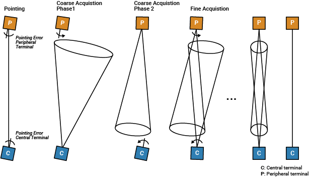
The PAT process consists of three phases.
Pointing — This phase involves identifying and correcting pointing errors at both the central and peripheral terminals to ensure the optical beam is directed toward the receiver.
Coarse acquisition — This phase consists of two sub-phases.
Phase 1 — The system uses a wide, cone-shaped, beam pattern to effectively locate and establish initial contact between the terminals, accommodating larger pointing errors.
Phase 2 — The beam cone narrows as the terminals begin to refine their alignment, reducing the search area and preparing for fine acquisition.
Fine acquisition — In this phase, the central terminal and peripheral terminal adjust their orientations to establish a precise optical connection for high-speed data transfer. The terminals reduce their beam to improve resolution and minimize pointing errors, making adjustments in smaller increments for nearly perfect alignment. This precise alignment captures the optical beam, improving signal reception. Throughout this process, both the central and peripheral terminals continually adjust their positions during tracking to maintain the optical signal and ensure uninterrupted communication.
Throughout all the phases, the system performs continuous tracking to maintain the established optical link.
PAT beacons use different wavelengths during initial acquisition. Large divergence angles enable the terminals to look even more efficiently for an optical beacon. High bandwidth and good stability with proper hardware, along with optimized control algorithms, ensure that the FSOC establishes stable and high-bandwidth optical links. The PAT mechanism helps efficiently manage power consumption while reliability in delivering data transmissions.
Detectors
Detectors help to capture and amplify weak signals that have been attenuated and
distorted by atmospheric channel conditions. Prominent detectors in FSOC systems include
avalanche photodiodes (APDs), photomultiplier tubes (PMTs), and superconducting nanowire
single-photon detectors (SNSPDs). The received photon counts at the photo detectors are
usually modeled using the Poisson channel, which simulates photon counting effects in deep
space communication by considering both signal and noise photons. For more information,
see dsocPoissonChannel.
APD — APDs are semiconductor devices that convert light into electrical energy through interband excitation combined with impact ionization. APDs are highly suited for high-speed and low-light-level operation, specifically designed to detect weak optical signals over long distances encountered in satellite and deep space communications. The Webb Gaussian channel model enhances APD analysis by modeling photodetector noise and performance under varied conditions. For more information, see
dsocWebbGaussianChannel.PMT — PMTs consist of a photocathode and a dynode. Dynodes are electrodes designed to multiply the number of electrons that work together to amplify weak optical signals. When a photon strikes the photocathode, it releases an electron. High-voltage electric fields then accelerate this electron toward a series of dynodes, resulting in significant signal amplification. Because of the high sensitivity of PMTs, they are useful for deep space missions where optical signals can be very weak.
SNSPD — SNSPD detectors are designed to detect single photons across the full optical and near-IR spectra. These sensors use nanowire superconductors biased just below their critical current to maintain a superconducting state. When a photon is absorbed, it raises the localized temperature, generating a detectable voltage pulse that signals its detection. The high sensitivity of the SNSPDs enables them to pick up very weak signals, while low dark count rates, which measure the number of false detection events in the absence of any incident light, enhance the integrity and reliability of data transmission, particularly in challenging environments where signal strength is important.
Deep Space Optical Communications (DSOC)
DSOC is an extension of FSOC, both utilizing similar technology to transmit data through light. However, while FSOC is primarily designed for applications closer to the Earth, DSOC focuses on deep space missions, enabling data transmission over vast distances. DSOC transmits data between spacecraft and ground stations over enormous distances across space through laser beams. DSOC enables large volumes of scientific data, images, and videos to be transferred back to the Earth. Missions focused on space and real-time data analysis, such as planetary exploration, space telescopes, and interplanetary missions, involve DSOC.
DSOC primarily operates in the near-IR wavelengths, with 1064 nm and 1550 nm being the two most common wavelengths used. Deep space communication favors the 1064 nm wavelength due to its excellent balance between atmospheric transmission and detector sensitivity. Meanwhile, very long distance space communications prefer the 1550 nm wavelength, which has similar properties to FSOC and offers reduced atmospheric attenuation and improved power efficiency.
Components of DSOC System
The DSOC system consists of three sections: an optical transceiver assembly (OTA) containing various optical elements, an isolation pointing assembly (IPA) for precise alignment, and a laser transmitter assembly (LTA) connected to electronics that handle signal processing and control.
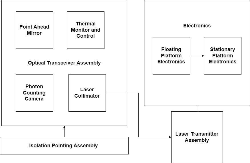
Laser transmitter assembly (LTA) — The LTA generates and boosts the laser pulses employed for communication. It transmits pulse trains, modulated with downlink data at high peak power for space-to-spacecraft communication links over long distances, and even with greater signal loss in space.
Optical transceiver assembly (OTA) — The OTA receives and transmits optical signals. The mirrors and lenses of the OTA focus the laser beams in the incoming and outgoing transmission, ensuring efficient transmission of data.
Laser collimator (LC) — The LC focuses and directs the data-carrying laser beam. The collimator aligns the light waves into a coherent beam, ensuring minimal dispersion as the laser traverses long distances in space, to maintain signal integrity during transmission.
Photon counting camera (PCC) — The PCC enables high-sensitivity measurements under low-light conditions, where it can detect individual photons with low dark noise and negligible read noise. This capability is essential in deep space communications, where signals tend to be extremely weak. The PCC can detect dim laser beacons sent from the Earth, enabling accurate reception of information.
Point ahead mirror (PAM) — The PAM points the optical downlink signal toward the anticipated position of the Earth for communication phase. It adjusts the directions of laser beams to correct for relative motion between spacecraft and the target, which ensures accurate pointing despite vast distances and the motion of the Earth and spacecraft.
Thermal monitor and control (TMC) — The TMC controls system component temperature and overheating conditions to provide optimal performance. Optical systems, especially those with lasers and photons, are generally sensitive to temperature, which can cause both performance and accuracy to degrade.
Isolation pointing assembly (IPA) — The IPA stabilizes and points the laser communication beam. The IPA isolates the telescope from the vibrations and additional disturbances that would otherwise introduce pointing inaccuracies. It also adjusts the pointing of the laser beam to enable successful transmission to the target, which could be the Earth or another spacecraft, with high accuracy.
Electronics — The electronics subsystem consists of the firmware and the software necessary to control the laser communication system. The electronics manage the power and distribution of clocks for stationary and moving components, and act as an interface for power and data transfer with the spacecraft. This ensures the laser communication components function properly and are integrated with the spacecraft systems.
Regulatory Organizations
Organizations have developed standards to support OWC and ensure effective data transmission. DSOC specifically has two current standards.
CCSDS
The CCSDS developed an optical communications working group that specifies three major scenarios.
HDR links — HDR links are targeted for near-earth missions, focusing on high data rates, and are particularly effective for applications such as space exploration and research. For an example of how to generate a CCSDS HDR waveform, see CCSDS Optical High Data Rate Waveform Generation for 1550nm.
HPE links — HPE links are suitable for deep space missions, where power and mass are constrained. HPE is designed for photon-starved links, where you must transmit data using very few photons due to both the large distances in deep space reducing the received photon count and the limited power and mass resources on spacecraft. Use the
ccsdsHPEWaveformGeneratorobject to generate a CCSDS optical HPE waveform. For an example of how to generate a CCSDS HPE waveform, see CCSDS Optical High Photon Efficiency Telemetry Waveform Generation.Low complexity systems — Low complexity systems are cost-effective systems that prioritize simplicity and lower costs instead of high performance. They are especially useful in scenarios where communication is affordable and less complex. These systems are ideal for low Earth orbit (LEO) direct-to-Earth (DTE) links.
SDA
The SDA is a US government organization that develops and deploys space technology for the Department of Defense. The SDA focuses on developing standardized documents and specifications, such as [7], to guide the implementation and interoperability of its space-based systems. For an example of how to generate the SDA optical communication terminal waveform, see SDA Optical Communication Terminal Waveform Generation.
References
[1] Kaushal, Hemani, et al. Free Space Optical Communication. Springer, 2017.
[2] Garlinska, Magdalena, et al. “From Mirrors to Free-Space Optical Communication—Historical Aspects in Data Transmission.” Future Internet, vol. 12, no. 11, Oct. 2020, p. 179. DOI.org (Crossref), https://doi.org/10.3390/fi12110179.
[3] CCSDS: Research and Development for Space Data System Standards — Optical High Data Rate (HDR) Communication 1064 NM.
[4] Edwards, Bernard L., et al. “An Update on the CCSDS Optical Communications Working Group.” 2017 IEEE International Conference on Space Optical Systems and Applications (ICSOS), IEEE, 2017, pp. 1–9. DOI.org (Crossref), https://doi.org/10.1109/ICSOS.2017.8357202.
[5] Abrahamsen, Fredrik Ege, et al. “Free-Space Optical Communication: From Space to Ground and Ocean.” IEEE Potentials, vol. 40, no. 6, Nov. 2021, pp. 18–23. DOI.org (Crossref), https://doi.org/10.1109/MPOT.2020.2979057.
[6] Deep Space Optical Communications by Tom Glavich.
[7] Space Development Agency: Optical Communications Terminal (OCT) Standard Version 3.1.0.
[8] Wu, Yue, et al. “Tbps Wide-Field Parallel Optical Wireless Communications Based on a Metasurface Beam Splitter.” Nature Communications, vol. 15, no. 1, Sept. 2024, p. 7744. www.nature.com, https://doi.org/10.1038/s41467-024-52056-4.
[9] Hamza, Abdelbaset S., et al. “OWCell: Optical Wireless Cellular Data Center Network Architecture.” 2017 IEEE International Conference on Communications (ICC), IEEE, 2017, pp. 1–6. DOI.org (Crossref), https://doi.org/10.1109/ICC.2017.7996501.
[10] “IEEE Standard for Information Technology–Telecommunications and Information Exchange between Systems Local and Metropolitan Area Networks–Specific Requirements Part 11: Wireless LAN Medium Access Control (MAC) and Physical Layer (PHY) Specifications Amendment 6: Light Communications.” IEEE Std 802.11bb-2023 (Amendment to IEEE Std 802.11-2020 as Amended by IEEE Std 802.11ax-2021, IEEE Std 802.11ay-2021, IEEE Std 802.11ba-2021, IEEE Std 802.11az-2022, IEEE Std 802.11-2020/Cor 1-2022, and IEEE Std 802.11bd-2023), Nov. 2023, pp. 1–37. IEEE Xplore, https://doi.org/10.1109/IEEESTD.2024.10315104.
[11] “IEEE Standard for Multi-Gigabit per Second Optical Wireless Communications (OWC), with Ranges up to 200 m, for Both Stationary and Mobile Devices.” IEEE Std 802.15.13-2023, Aug. 2023, pp. 1–158. IEEE Xplore, https://doi.org/10.1109/IEEESTD.2023.10205961.