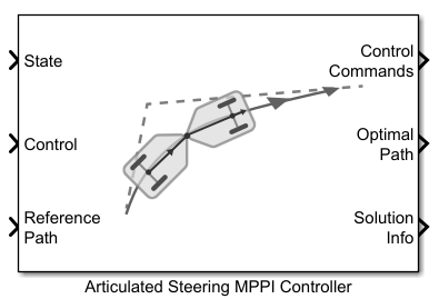
Articulated Steering MPPI Controller
Control motion planning of articulated steering vehicle model using Model Predictive Path Integral (MPPI)
Since R2025b
Libraries:
Offroad Autonomy Library /
Vehicle Controllers
Description
The Articulated Steering MPPI Controller block enables you to plan a local
path for a vehicle modeled with articulatedSteeringKinematics object. The block uses the model predictive path
integral (MPPI) algorithm and follows a reference path, typically generated by a global
planner such as RRT* or Hybrid A*.
The articulated steering vehicle model represents a vehicle with an articulated joint and two axles. The front axle is at an offset specified by the Front Angle Offset (m) parameter from the articulated joint. The rear axle is at an offset specified by the Rear Angle Offset (m) parameter from the articulated joint. The articulated joint is active, which means the steering occurs by controlling the articulation angle between the front and rear bodies. The state of the vehicle is defined as a four-element vector, [x y thetaFront gamma], with the coordinates of the middle of the front axle, xy, specified in meters, the front body orientation, thetaFront, and the articulation or steering angle, gamma, specified in radians. The articulation angle is defined as the front body steering relative to the rear body.
The heading of the rear body, thetaRear, is derived from the front body heading and the articulation angle as:
thetaRear = thetaFront - gamma
All angles are measured positive in the counterclockwise direction. Accordingly, a clockwise rotation of the front body relative to the rear body results in a negative articulation angle, whereas, a counterclockwise rotation results in a positive articulation angle as shown in the vehicle model diagram below.
The MPPI controller runs at the block sample time. At each update, the controller samples control sequences, propagates them to generate potential trajectories, evaluates the trajectories with a cost function, and computes the optimal control command. For best performance, you must run the controller at a high frequency.
Examples

Plan Path Using Articulated Steering MPPI Controller in Simulink
Follow an obstacle-free path with an articulated steering vehicle model between two locations on a given map in Simulink®.
Ports
Input
Output
Parameters
Extended Capabilities
Version History
Introduced in R2025b