microstripLine
Description
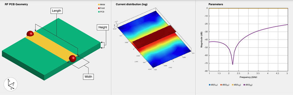
Use the microstripLine object to create a microstrip transmission
line. A microstrip line is a transmission line that is a basic building block for most RF
planar microwave devices. You can use this transmission line to connect two PCB components or
to create components such as filters, couplers, and feeding elements of various types of
antennas.
Note
This PCB object supports behavioral modeling. For more information, see Behavioral Models. To analyze the behavioral
model for a microstrip transmission line, set the Behavioral property
in the sparameters
function to true or 1
A few applications of microstrip transmission lines are:
Creating matching feed and coupling networks
Transmitting power from one component to another
Feeding planar antennas and coupling structures
Creating varying inductances or capacitances using open- or short ended- transmission lines
Creation
Syntax
Description
microstrip = microstripLine creates a default microstrip
transmission line using a Teflon substrate.
microstrip = microstripLine(
sets properties using one or more name value pair arguments. For example,
PropertyName=Value)microstrip = microstripLine(Length=0.0300) creates a microstrip
line of length 0.0300 meters. Properties not specified retain their default
values.
microstrip = microstripLine(
creates a microstrip transmission line from the behavioral model of a txlineobj)txlineMicrostrip
object in RF Toolbox™.
Properties
Object Functions
charge | Calculate and plot charge distribution |
current | Calculate and plot current distribution |
design | Design microstrip transmission line around specified frequency |
feedCurrent | Calculate current at feed port |
getZ0 | Calculate characteristic impedance of transmission line |
layout | Plot all metal layers and board shape |
mesh | Change and view mesh properties of metal or dielectric in PCB component |
propagationDelay | Compute propagation delay of transmission line |
rlgc | Compute resistances, inductances, conductances, and capacitances |
shapes | Extract all metal layer shapes of PCB component |
show | Display PCB component structure or PCB shape |
sparameters | Calculate S-parameters for RF PCB objects |
RFConnector | Create RF connector |
Examples
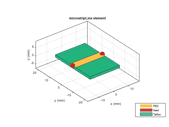
Create and view a default microstrip transmission line.
microstrip = microstripLine
microstrip =
  microstripLine with properties:

              Length: 0.0200
               Width: 0.0050
              Height: 0.0016
    GroundPlaneWidth: 0.0300
           Substrate: [1×1 dielectric]
           Conductor: [1×1 metal]
          IsShielded: 0
show(microstrip)
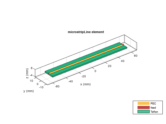
Design a microstrip transmission line at 3 GHz, with a characteristic impedance of 70 ohms and a line length 1.5 times the wavelength.
microstrip = design(microstripLine,3e9,'Z0',70,'LineLength',1.5)
microstrip =
  microstripLine with properties:

              Length: 0.1132
               Width: 0.0030
              Height: 0.0016
    GroundPlaneWidth: 0.0150
           Substrate: [1×1 dielectric]
           Conductor: [1×1 metal]
          IsShielded: 0
View the microstrip transmission line.
show(microstrip)
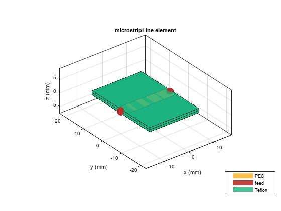
Create and view a multilayer dielectric microstrip transmission line.
microstrip = microstripLine;
microstrip.Substrate = dielectric('Name',{'Teflon','Teflon'},'EpsilonR', ...
    [2.1 2.1],'LossTangent',[0 0],'Thickness',[0.8e-3 0.8e-3]);
    microstrip.Height = 0.8e-3;
show(microstrip);
Design a microstrip transmission line at 3 GHz using FR4 substrate.
d = dielectric('FR4');
d.LossTangent = 0;
m = design(microstripLine('Substrate',d),3e9,'Z0',75,...
    'LineLength',0.5);
Create a microstrip cross.
layer2d = traceCross('Length',[m.Length m.Length], ...
    'Width',[m.Width m.Width]);
Convert the cross trace to a PCB component.
robj = pcbComponent(layer2d);
robj.BoardThickness = m.Substrate.Thickness;
robj.Layers{2} = m.Substrate;
show(robj)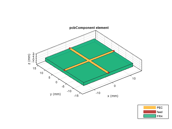
Define frequency points to calculate the s-parameters.
freq = (1:3:40)*100e6;
Calculate the s-parameters of the cross trace using the behavioral model.
Sckt = sparameters(robj,freq,'Behavioral',true);Warning: Behavioral model is valid only when EpsilonR is 9.9.
Calculate the s-parameters of the cross trace using the electromagnetic solver.
Sem = sparameters(robj,freq);
References:
Ramesh Garg & I. J. Bahl (1978) Microstrip discontinuities, International Journal of Electronics, 45:1, 81-87, DOI: 10.1080/00207217808900883
Wadell, Brian C. Transmission Line Design Handbook. The Artech House Microwave Library. Boston: Artech House, 1991.
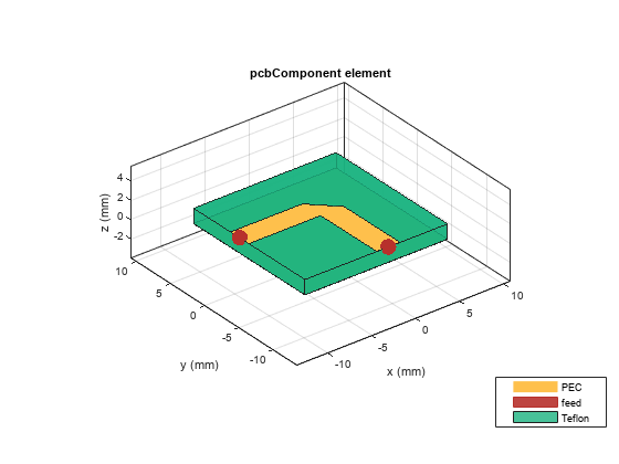
Create mitered bend microstrip.
m = design(microstripLine,6e9,"Z0",75);
layer2d = bendMitered('Length',[m.Length/2 m.Length/2],...
"Width",[m.Width m.Width],'MiterDiagonal',sqrt(2)*m.Width);
robj = pcbComponent(layer2d);
robj.BoardThickness = m.Substrate.Thickness;
robj.Layers{2} = m.Substrate;
show(robj)
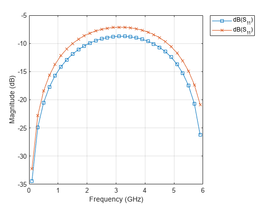
Compute and plot s-parameters.
freq = (1:2:60)*100e6;
Sckt = sparameters(robj,freq,'Behavioral',true);
Sem = sparameters(robj,freq);
rfplot(Sckt,1,1,'db','-s')
hold on
rfplot(Sem,1,1,'db','-x')
Reference:
M. Kirschning, R. H. Jansen and N. H. L. Koster, "Measurement and Computer-Aided Modeling of Microstrip Discontinuities by an Improved Resonator Method," 1983 IEEE MTT-S International Microwave Symposium Digest, Boston, MA, USA, 1983, pp. 495-497, doi: 10.1109/MWSYM.1983.1130959.
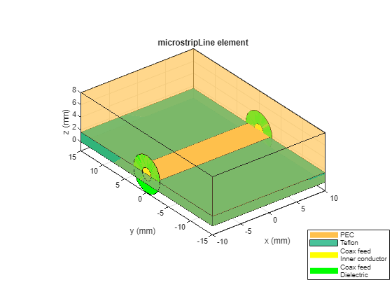
Create a microstrip transmission line with a metal shield.
microstrip = microstripLine(IsShielded=true)
microstrip =
  microstripLine with properties:

              Length: 0.0200
               Width: 0.0050
              Height: 0.0016
    GroundPlaneWidth: 0.0300
           Substrate: [1×1 dielectric]
           Conductor: [1×1 metal]
          IsShielded: 1
           Connector: [1×1 RFConnector]
           Shielding: [1×1 shape.Box]
Display the Connector property whose value is set to a default RFConnector.
microstrip.Connector
ans =
  RFConnector with properties:

            Name: 'Connector'
     InnerRadius: 4.7800e-04
     OuterRadius: 0.0016
          Flange: [1×1 antenna.Rectangle]
        EpsilonR: 2.0971
    PinFootprint: 'Taper'
       PinLength: 0.0030
       Impedance: 50
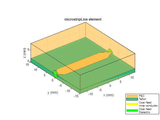
View a microstrip transmission line. A tapered trace is added to the both ends of the microstrip transmission line - tapered from a trace width of a microstrip transmission line to an inner diameter of a connector. The length of a tapered trace is controlled by the PinLength property.
show(microstrip)
Set the PinLength property to zero and view a microstrip transmission line. Beware that an outer conductor of a connector must not electrically connected to the signal trace.
microstrip.Connector.PinLength = 0;
microstrip.Connector.OuterRadius = 0.003;
microstrip.Connector.InnerRadius = 0.001;
show(microstrip)
References
[1] Pozar, David M. Microwave Engineering. 4th ed. Hoboken, NJ: Wiley, 2012.