Design IF Butterworth Bandpass Filter
This example shows how to design an Intermediate Frequency (IF) Butterworth bandpass filter with a center frequency of 400 MHz, bandwidth of 5 MHz, and Insertion Loss (IL) of 1dB [1].
Account for Mismatch/Insertion Loss (IL)
Practical circuits suffer a certain degree of mismatch. Mismatch happens when an unmatched circuit is connected to an RF source leading to reflections that result in a loss of power delivered to the circuit. You can use IL to define this mismatch. Calculate the load impedance mismatch to account for the given IL. The IL and normalized load impedance (ZL) are related as follows [2],[3]:
IL (dB) = -10*log10(1-| |^2) = -10*log10(4*ZL/(1+ZL)^2)
The roots of the resulting polynomial return the value of normalized load impedance. The unnormalized values are 132.986 Ohms and 18.799 Ohms. Choose the higher value for the filter design to account for the IL.
syms ZL IL
eqn = -10*log10(4*ZL/(1+ZL)^2) - IL == 0;
[solx, ~, ~] = solve(eqn,ZL,'ReturnConditions', true);
IL_desired_dB = 1;
Zload = double(subs(solx,IL,IL_desired_dB))*50;
Load impedance:
ZL = Zload(2);
Design Filter
Use rffilter to design the filter for the desired specifications.
Fcenter = 400e6;
Bwpass  = 5e6;
if_filter = rffilter('ResponseType','Bandpass',...
    'FilterType','Butterworth','FilterOrder',4,...
    'PassbandAttenuation',10*log10(2),...
    'Implementation','Transfer function',...
    'PassbandFrequency',[Fcenter-Bwpass/2 Fcenter+Bwpass/2],'Zout',ZL);
Plot S-parameters and Group Delay of Filter
Calculate S-parameters.
freq = linspace(370e6,410e6,2001);
Sf = sparameters(if_filter, freq);
figure;
line = rfplot(Sf);
lgd = legend;
lgd.Location = "best";
[~,freq_index] = min(abs(freq-Fcenter));
datatip(line(3),'DataIndex',freq_index);
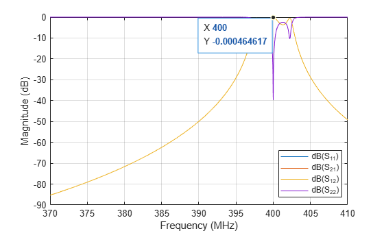
A datatip shows a 1dB IL at Fcenter = 400 MHz.
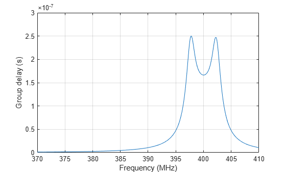
Calculate groupdelay:
gd = groupdelay(if_filter, freq);
figure;
plot(freq/1e6, gd);
xlabel('Frequency (MHz)');
ylabel('Group delay (s)');
grid on;
Insert Filter into rfbudget Object
An rffilter object can be inserted directly into an rfbudget object to perform budget analysis.
rfb = rfbudget(if_filter,Fcenter,-30,Bwpass)
rfb =
  rfbudget with properties:

               Elements: [1x1 rffilter]
         InputFrequency: 400 MHz
    AvailableInputPower: -30 dBm
        SignalBandwidth:   5 MHz
                 Solver: Friis
             AutoUpdate: true

   Analysis Results
        OutputFrequency:        400 (MHz)
            OutputPower:        -30 (dBm)
         TransducerGain: -0.0004646 (dB)
                     NF:          0 (dB)
                   IIP3:        Inf (dBm)
                   OIP3:        Inf (dBm)
                    SNR:      76.99 (dB)
References
[1] Hongbao Zhou, Bin Luo. " Design and budget analysis of RF receiver of 5.8GHz ETC reader" Published at Communication Technology (ICCT), 2010 12th IEEE International Conference, Nanjing, China, November 2010.
[2] Electronic Filter Analysis and Synthesis, Michael G. Ellis, Sr., Artech House, Chapter 7.
[3] RF Circuit Design, R. Ludwig, G. Bogdanov, Pearson Education, Chapter 2.