CAN FD Transmit
R2026bCAN FD Transmit block
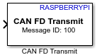
To add a block to a model, double-click the canvas and start typing the block name. Then, select the block from the list.
Libraries:
Raspberry Pi Blockset /
Communication
Description
The CAN FD Transmit block transmits messages over a Controller Area Network Flexible Data Rate (CAN FD) interface from a Simulink® model. Use this block to send CAN FD frames from Raspberry Pi® hardware through a configured CAN interface. CAN FD extends classical CAN by enabling larger CAN FD message sizes and higher data rates allowing efficient transmission of high-volume data.
The block supports two input workflows:
Raw CAN FD message transmission using a
uint8vector.Message-based transmission using a structured CAN FD message. Use the CAN FD Pack (Embedded Coder) block to define the message fields.
The block supports CAN FD message sizes up to 64 bytes and allows transmission at higher data rates during the data phase using bit rate switching.
Note
To generate C/C++ code for this block, you must have an Embedded Coder® license.
The CAN FD Transmit block can also transmit classical CAN messages when the interface is configured for CAN FD. To transmit classical CAN messages, do not use bit rate switching and make sure the message size is 8 bytes or less.
For more information on how to enable the SPI interface and configure the MCP2518FD CAN FD controller for CAN FD configuration, see Enable and Configure Raspberry Pi for SPI and CAN FD Communication Using Waveshare 2-CH CAN FD HAT.
Examples
Transmit a CAN FD message.
Use this workflow to directly send byte-level data without constructing a structured CAN FD message. In this mode, the block transmits the input vector as the data field of a CAN FD frame.
In the CAN FD Transmit block, set Data is input
as to Raw data to enable direct CAN FD message
transmission using a byte vector.
Specify Message length based on the number of bytes to transmit. Use a value to match one of the supported CAN FD message sizes.
Provide a uint8 vector input whose length matches the specified
message length. Each element of the vector represents one byte in the CAN FD
message.
(Optional) Configure additional message parameters such as:
Identifier type — Standard or Extended
Enable bit rate switching for higher data throughput
Run the model to transmit the CAN FD frame over the configured CAN interface.
During simulation, the block packages the input vector into a CAN FD frame using the specified message parameters and transmits it over the selected interface. If bit rate switching is enabled, the message is transmitted at a higher data rate during the data phase.
Transmit a CAN FD message using a message-based workflow.
Use this workflow to construct and transmit CAN FD frames using a structured message format which enables explicit configuration of message fields such as identifier, message length, and CAN FD-specific flags. In this mode, the CAN FD Transmit block accepts a Simulink bus signal that represents a complete CAN FD message. The message structure is typically created using a CAN FD Pack (Embedded Coder) block which provides a consistent interface for specifying frame attributes.
Add a CAN FD Pack (Embedded Coder) block to your Simulink model.
Connect the output of the CAN FD Pack (Embedded Coder) block to the input port of the CAN FD Transmit block.
In the CAN FD Transmit block, set Data is input
as to CAN Msg to enable the block to accept
structured message input.
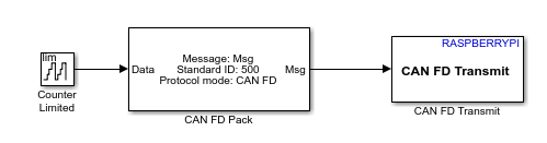
Configure these message fields in the CAN FD Transmit block:
Identifier type — Standard or Extended
Run the model to transmit CAN FD messages.
During simulation, the CAN FD Transmit block forwards the structured CAN FD message to the configured CAN interface. All frame properties, including identifier, message, and flags, are derived directly from the input bus. The block preserves these values and transmits the message without any modification.
Transmit CAN FD messages at higher data rates.
Use this workflow to increase the effective data throughput of CAN FD communication. CAN FD supports transmitting the data phase of a frame at a higher bit rate than the arbitration phase using bit rate switching.
In the CAN FD Transmit block, select Enable bit rate switching to transmit CAN FD frames using an increased data rate during the data phase.
Configure the CAN interface with appropriate nominal and data bit rates.
Run the model to transmit the CAN FD message.
During transmission, the block sends CAN FD frames using the nominal bit rate for arbitration. When bit rate switching is enabled, the block transmits the data at a higher bit rate during the data phase, resulting in improved communication efficiency.
Extended Examples
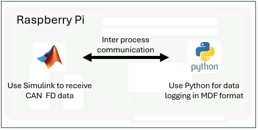
Log CAN Bus Data on Raspberry Pi
Use Raspberry Pi® Blockset to monitor a controller area network (CAN) bus, perform basic CAN conversions, and log CAN FD data in a measurable data format (MDF) file. This example also showcases the interoperability between a model deployed in Simulink® and a Python® program running simultaneously on Raspberry Pi hardware.
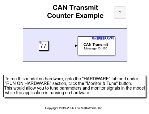
Transmit and Receive Data Using Raspberry Pi CAN Blocks
To use Raspberry Pi® Blockset to transmit and receive data from the CAN network using the specified CAN device.
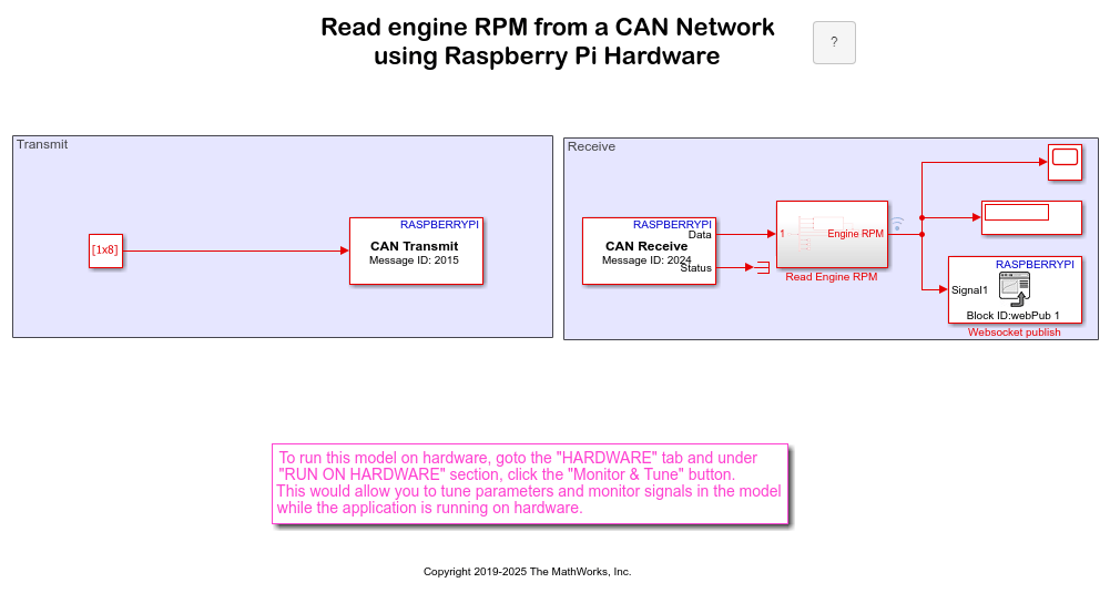
Monitor Engine RPM Using Raspberry Pi CAN Blocks
Use Raspberry Pi® Blockset to monitor vehicle engine RPM and read the data on a web browser.
Ports
Input
Output
Parameters
Extended Capabilities
Version History
Introduced in R2026b

