Gate Valve (MA)

Libraries:
Simscape /
Fluids /
Moist Air /
Valves & Orifices /
Flow Control Valves
Description
The Gate Valve (MA) block represents an orifice with a translating gate, or sluice, as a flow control mechanism. The gate is circular and must slide perpendicular to the flow due to the constrains of the groove of its seat. The seat of the valve is annular. The flow passes through the bore, which is sized to match the gate. The overlap of the gate and the bore determines the opening area of the valve.
The flow can be laminar or turbulent, and it can reach up to sonic speeds. The maximum velocity happens at the throat of the valve where the flow is narrowest and fastest. The flow chokes and the velocity saturates when a drop in downstream pressure can no longer increase the velocity. Choking occurs when the back-pressure ratio reaches the critical value characteristic of the valve. The block does not capture supersonic flow.
Gate valves generally open quickly. Gate valves are most sensitive to gate displacement near the closed position, where a small displacement translates into a disproportionately large change in opening area. Consequently, gate valves have too high a gain in that region to effectively throttle or modulate flow. You can use this block as a binary switch to open and close moist air flows.
Gate Mechanics
In a real valve, the gate connects by a gear mechanism to a handle. When the handle is turned from a fully closed position, the gate rises from the bore and progressively opens the valve up to a maximum. Hard stops keep the disk from breaching its minimum and maximum positions.
The block captures the motion of the disk but not the detail of its mechanics. You specify the motion as a normalized displacement at port S. The input physical signal carries the fraction of the instantaneous displacement over its value in the fully open valve.
If you want to model the action of the handle and hard stop, use Simscape mechanical blocks to capture the displacement signal. However, in many cases, it suffices to know what displacement to impart to the disk and you do not need to model the mechanics of the valve.
Gate Position
The block models the displacement of the gate but not the valve opening or closing dynamics. The signal at port S provides the gate position.
When the Smoothing factor parameter is nonzero, the block applies numerical smoothing to the normalized gate position. Enabling smoothing helps maintain numerical robustness in your simulation.
For more information, see Numerical Smoothing.
Opening Area
The area open to flow as the gate retracts is:
where d0 is the Valve orifice diameter. The area shielded by the gate in a partially open valve is:
where Δl is the gate displacement, which is the sum of the signal at port S and the Gate position when fully covering orifice.
The figure shows a front view of the valve when maximally closed, partially open, and fully open, from left to right. The figure also shows the parameters and variables in the opening area calculation.
Valve Parameterizations
The block behavior depends on the Valve parametrization parameter:
Cv flow coefficient— The flow coefficient Cv determines the block parameterization. The flow coefficient measures the ease with which the moist air can flow when driven by a certain pressure differential.Kv flow coefficient— The flow coefficient Kv, where , determines the block parameterization. The flow coefficient measures the ease with which the moist air can flow when driven by a certain pressure differential.Sonic conductance— The sonic conductance of the resistive element at steady state determines the block parameterization. The sonic conductance measures the ease with which the moist air can flow when choked, which is a condition in which the flow velocity is at the local speed of sound. Choking occurs when the ratio between downstream and upstream pressures reaches a critical value known as the critical pressure ratio.Orifice area based on geometry— The size of the flow restriction determines the block parametrization.
The block scales the specified flow capacity by the fraction of valve opening. As
the fraction of valve opening rises from 0 to
1, the measure of flow capacity scales from its specified
minimum to its specified maximum.
Momentum Balance
The block equations depend on the Valve parameterization parameter.
When you set Valve parameterization to Cv flow
coefficient, the mass flow rate, , is
where:
Cv is the value of the Maximum Cv flow coefficient parameter.
Sopen is the valve opening area.
SMax is the maximum valve area when the valve is fully open.
N6 is a constant equal to 27.3 for mass flow rate in kg/hr, pressure in bar, and density in kg/m3.
Y is the expansion factor.
pin is the inlet pressure.
pout is the outlet pressure.
ρin is the inlet density.
The expansion factor is
where:
Fγ is the ratio of the isentropic exponent to 1.4.
xT is the value of the xT pressure differential ratio factor at choked flow parameter.
The block smoothly transitions to a linearized form of the equation when the pressure ratio, , rises above the value of the Laminar flow pressure ratio parameter, Blam,
where:
When the pressure ratio, , falls below , the orifice becomes choked and the block switches to the equation
When you set Valve parameterization to Kv flow
coefficient, the block uses these same equations, but replaces
Cv with
Kv by using the relation . For more information on the mass flow equations when the
Valve parameterization parameter is Kv
flow coefficient or Cv flow
coefficient, [2][3].
When you set Valve parameterization to Sonic
conductance, the mass flow rate, , is
where:
C is the value of the Maximum sonic conductance parameter.
Bcrit is the critical pressure ratio.
m is the value of the Subsonic index parameter.
Tref is the value of the ISO reference temperature parameter.
ρref is the value of the ISO reference density parameter.
Tin is the inlet temperature.
The block smoothly transitions to a linearized form of the equation when the pressure ratio, , rises above the value of the Laminar flow pressure ratio parameter Blam,
When the pressure ratio, , falls below the critical pressure ratio, Bcrit, the orifice becomes choked and the block switches to the equation
The Sonic conductance setting of the
Valve parameterization parameter is for pneumatic
applications. If you use this setting for moist air with high levels of trace
gasses or are modeling a fluid other than air, you may need to scale the sonic
conductance by the square root of the mixture specific gravity.
For more information on the mass flow equations when the Valve
parameterization parameter is Sonic
conductance, see [1].
When you set Valve parameterization to Orifice area
based on geometry, the mass flow rate, , is
where:
Sopen is the valve opening area.
S is the value of the Cross-sectional area at ports A and B parameter.
Cd is the value of the Discharge coefficient parameter.
γ is the isentropic exponent.
The block smoothly transitions to a linearized form of the equation when the pressure ratio, , rises above the value of the Laminar flow pressure ratio parameter, Blam,
When the pressure ratio, , falls below , the orifice becomes choked and the block switches to the equation
For more information on the mass flow equations when the Valve
parameterization parameter is Orifice area based on
geometry, see [4].
Mass Balance
The block conserves mass through the valve
where ṁ is the mass flow rate and the subscript w denotes water vapor, the subscript g denotes trace gas, and the subscript d denotes water droplets.
Energy Balance
The resistive element of the block is an adiabatic component. No heat exchange can occur between the fluid and the wall that surrounds it. No work is done on or by the fluid as it traverses from inlet to outlet. Energy can flow only by advection, through ports A and B. By the principle of conservation of energy, the sum of the port energy flows is always equal to zero
where ϕ is the energy flow rate into the valve through ports A or B.
Assumptions and Limitations
This block does not model supersonic flow.
Examples
This example uses test harnesses to compare the Ball Valve (MA), Gate Valve (MA), and Poppet Valve (MA) blocks. A test harness is a minimum viable model that you can use to parameterize blocks or isolate dynamics.
Model
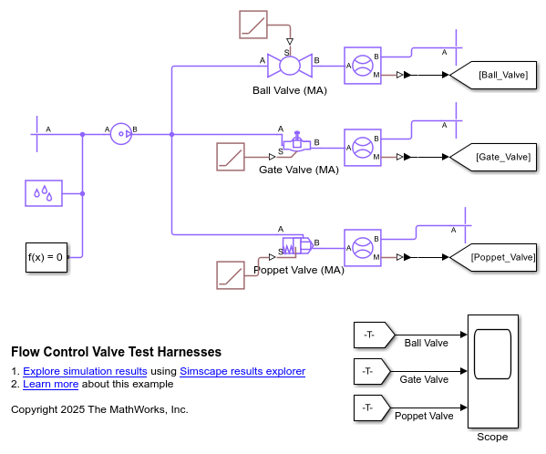
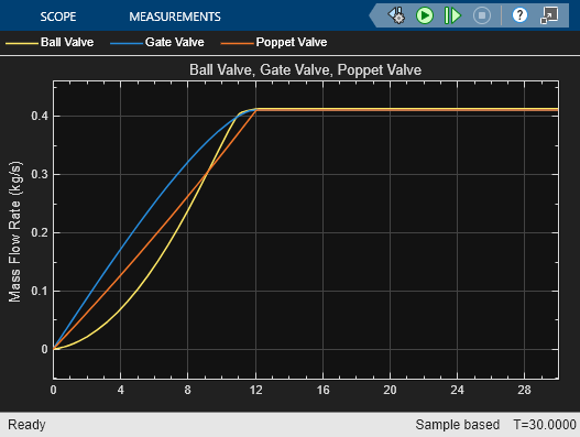
Simulation Results from Scopes
This figure shows the mass flow rate through each of the valves. All three valves start closed and slowly open before reaching their maximum area. At the maximum area, the mass flow rate also reaches its maximum and cannot increase further. Each curve has a different profile while opening because each valve has a different area profile that depends on the valve geometry.
Ports
Input
Conserving
Parameters
References
[1] ISO 6358-3, "Pneumatic fluid power – Determination of flow-rate characteristics of components using compressible fluids – Part 3: Method for calculating steady-state flow rate characteristics of systems", 2014.
[2] IEC 60534-2-3, “Industrial-process control valves – Part 2-3: Flow capacity – Test procedures”, 2015.
[3] ANSI/ISA-75.01.01, “Industrial-Process Control Valves – Part 2-1: Flow capacity – Sizing equations for fluid flow underinstalled conditions”, 2012.
[4] P. Beater, Pneumatic Drives, Springer-Verlag Berlin Heidelberg, 2007.
Extended Capabilities
Version History
Introduced in R2025a