4-Way 3-Position Directional Valve (MA)

Libraries:
Simscape /
Fluids /
Moist Air /
Valves & Orifices /
Directional Control Valves
Description
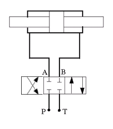
The 4-Way 3-Position Directional Valve (MA) block models a valve with four openings in a moist air network, typically between an actuator, pump, and tank. A single spool controls the valve operation according to the signal at port S. You can set the baseline configuration of your valve by specifying the orifices that are open when the spool is in the neutral position (centered at 0 m) in the Neutral spool position open connections parameter, when the spool moves in the positive direction in the Positive spool position open connections parameter, and when the spool moves in the negative direction in the Negative spool position open connections parameter. You can use the Orifice parameterization parameter to specify the valve model as a linear relationship or function of user-provided data.
This block is a composite component that comprises of multiple instances of the Orifice (MA) block. For more information about the valve parameterizations and block calculations, see the Orifice (MA) block.
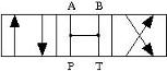
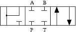
In this example configuration, the Neutral spool position open
connections parameter is All closed. When the
spool is in the neutral position, all orifices are closed to flow:
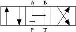
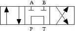
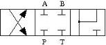
In this configuration, Negative spool position open connections
is P-A, B-T. When the signal at port S
moves the spool to a negative position, the paths between ports P
and A and between ports B and
T are open to flow. The paths between ports
P and B and ports A
and T are closed to flow:
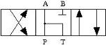
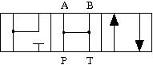
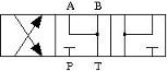
In this configuration, Positive spool position open connections
is P-B, A-T. When the signal at port S
moves the spool to a positive position, the paths between ports P
and B and between ports A and
T are open to flow and the paths between ports
P and A and between ports
B and T are closed:
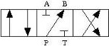
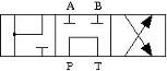
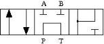
This schematic shows this configuration:
The left side corresponds to the positive position and the right side corresponds to the negative position.
Spool Displacement and Valve Configuration
The spool stroke is the amount of spool travel an orifice takes to fully open from a closed position. You can define the spool stroke using the parameters in the Valve Configuration section. The table shows how the block calculates the stroke in accordance with the valve orifice parameterization and flow path characteristics.
The direction of spool movement specified by port S depends on the spool stroke and the orifice orientation.
| Spool Position When Orifice Is Open | Spool Travel, ΔS |
|---|---|
| Always closed (orifice is not selected in any spool position configuration) | N/A |
| Always open (orifice is selected in positive, neutral, and negative spool position configurations) | N/A |
| Negative | Sorifice_max + spool stroke – S |
| Negative and Neutral | Sorifice_max + spool stroke – S |
| Positive | Sorifice_max – spool stroke + S |
| Positive and Neutral | Sorifice_max – spool stroke + S |
| Neutral | |Sorifice_max| + spool stroke – |S| |
| Positive and Negative | –|Sorifice_max| + spool stroke – |S| |
Sorifice_max is the spool position at the maximum orifice area defined for each orifice. The orifice area saturates at the leakage area when ΔS is negative and saturates at the maximum orifice area when the orifice is fully open. When the orifice is fully open, ΔS is equal to the spool stroke, so a value of ΔS that is greater than the spool stroke does not further increase the orifice area.
The Consistency check for neutral spool position open connections parameter verifies that:
Any orifice listed in Neutral spool position open connections is open when the signal at S is 0
Any orifice that is not listed in Neutral spool position open connections is closed when the signal at S is 0
You can optionally choose to receive a warning or error when any spool positions violate this check.
This table shows the possible configurations of the 4-Way 3-Position Directional Valve (MA) block.
| Configuration | Parameter Values |
|---|---|
| All four orifices are closed in the neutral position.
|
| All four orifices are open in the neutral position.
|
| Orifices A-T and B-T are closed. Orifices P-A and P-B are overlapped.
|
| Orifices A-T and B-T are open. Orifices P-A and P-B are overlapped.
|
| Orifices P-A and A-T are open in the neutral position. Orifices P-B and B-T are overlapped.
|
| Orifice A-T is open in the neutral position. Orifices P-B, A-T, and B-T are overlapped.
|
| Orifice B-T is open in the neutral position. Orifices P-A, P-B, and A-T are overlapped.
|
| Orifices P-A and P-B are open. Orifices A-T and B-T are overlapped.
|
| Orifice P-A is open in the neutral position. Orifices P-B, A-T, and B-T are overlapped.
|
| Orifice P-B is open in the neutral position. Orifices P-A, A-T, and B-T are overlapped.
|
| Orifices P-B and B-T are open in the neutral position. Orifices P-A and A-T are overlapped.
|
| Orifices P-A, P-B, A-T, and B-T are closed in the neutral position. P-T is open in the neutral position and closes when the spool displaces.
|
| Orifice P-A is a constant orifice. Orifices P-B, A-T, and B-T are open in the neutral position.
|
| Orifice P-B is a constant orifice. Orifices P-A, A-T, B-T are open in the neutral position.
|
| Orifice P-A is closed in the neutral position. Ports A and T do not form a flow path.
|
| Orifice P-B is closed in the neutral position. Ports B and T do not form a flow path.
|
| Orifice P-A is closed in the neutral position. Orifice A-T is open in the neutral position.
|
| Orifice P-B is closed in the neutral position. Orifice B-T is open in the neutral position.
|
| Orifice P-B is closed in the neutral position. Orifice P-T is open in the neutral position. Ports A and T do not form a flow path.
|
| Orifice P-A is closed in the neutral position. Orifice P-T is open in the neutral position. Ports A and T do not form a flow path.
|


Valve Orifice Parameterizations
The Orifice parameterization parameter specifies the model
for the open area or flow rate through one or all of the valve orifices. If you set
Area characteristics to Identical for all flow
paths, the block applies the same data for all flow paths. When
you select Different for all flow paths, the block uses
individual parameterizations for each flow path.
The method the block uses to control each orifice depends on the Opening characteristic parameter:
Linear— The measure of flow capacity depends on the spool position at port S. As the spool displaces to open to orifice, the measure of flow capacity scales from the specified minimum to the specified maximum.Tabulated— The block calculates the measure of flow capacity as a function of the spool position at port S. This function uses a one-dimensional lookup table.
The Orifice parameterization parameter determines how the block calculates the flow rate in each orifice:
Cv flow coefficient— The flow coefficient Cv scales the flow rate in each orifice. The flow coefficient measures the ease with which a fluid can flow when driven by a certain pressure differential.Kv flow coefficient— The flow coefficient Kv, where , scales the flow rate in each orifice. The flow coefficient measures the ease with which a fluid can flow when driven by a certain pressure differential.Orifice area— The size of the orifice area scales the flow rate in each orifice.
Visualize Orifice Openings
To generate a characteristic plot of the valve, click the Plot button next to Valve characteristics. The plot shows the orifices selected in the Valve Configuration settings. The plot shows the sonic conductance, Kv flow coefficient, Cv flow coefficient, or orifice area as a function of spool position.
When the positive, neutral, and negative settings in the Valve Configuration parameters feature the same orifice, the plot displays the orifice openings as a constant.
To update the data after changing the block parameters, click Reload Data on the figure window.
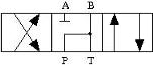
This image shows an example valve configuration. In the Valve Configuration settings:
Positive spool position open connections is
P-A,
												B-T
Neutral spool position open connections is
P-TNegative spool position open connections is
P-B,
												A-T
In the P-A Orifice settings:
Spool position at maximum P-A orifice area is
2.5e-3 m
All other spool positions are at the default values.
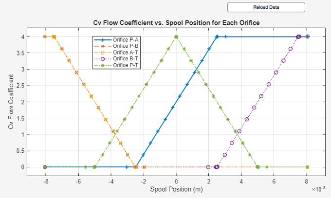
The visualization shows that the P-A orifice is open between the spool position at
-2.53e-3 and 2.53e-3 m. Because the P-A
orifice is open only when the spool is displaced in the positive direction, setting
the Consistency check for neutral spool and position open
connections parameter to Warning
returns:
Warning: P-A orifice must be closed when the spool is in
					the neutral position. Adjust Spool position at maximum P-A orifice area, Neutral
					spool position open connections, or Consistency check for neutral spool position
					open connections. Right-click on the block and select Fluids > Plot Valve
					Characteristics to view the area or flow of each connection versus spool
					position.
To resolve this warning, you can change:
Spool position at maximum P-A orifice area to a value larger than 0.005 m
Consistency check for neutral spool position open connections to
NoneThe valve configuration by setting Neutral spool position open connections to
P-A
Assumptions and Limitations
The
Sonic conductancesetting of the Valve parameterization parameter is for pneumatic applications. If you use this setting for moist air with high levels of trace gasses or are modeling a fluid other than air, you may need to scale the sonic conductance by the square root of the mixture specific gravity.This block does not model supersonic flow.
There is no heat exchange between the valve and the environment.
Ports
Conserving
Input
Parameters
References
[1] ISO 6358-3. "Pneumatic fluid power – Determination of flow-rate characteristics of components using compressible fluids – Part 3: Method for calculating steady-state flow rate characteristics of systems". 2014.
[2] IEC 60534-2-3. "Industrial-process control valves – Part 2-3: Flow capacity – Test procedures". 2015.
[3] ANSI/ISA-75.01.01. "Industrial-Process Control Valves – Part 2-1: Flow capacity – Sizing equations for fluid flow underinstalled conditions". 2012.
[4] P. Beater. Pneumatic Drives. Springer-Verlag Berlin Heidelberg. 2007.
Extended Capabilities
Version History
Introduced in R2025a