2-Way Directional Valve (MA)

Libraries:
Simscape /
Fluids /
Moist Air /
Valves & Orifices /
Directional Control Valves
Description
The 2-Way Directional Valve (MA) block represents a valve with two ports, A and B, and one flow path, A–B. The path runs through an orifice of variable width. The input signal specified at port S controls the position of the spool. The valve closes when the spool covers the orifice opening. For more details about how the block calculates flow rate through a variable orifice, see Orifice (MA).
Valve Parameterizations
The block behavior depends on the Valve parametrization parameter:
Cv flow coefficient— The flow coefficient Cv determines the block parameterization. The flow coefficient measures the ease with which the moist air can flow when driven by a certain pressure differential.Kv flow coefficient— The flow coefficient Kv, where , determines the block parameterization. The flow coefficient measures the ease with which the moist air can flow when driven by a certain pressure differential.Sonic conductance— The sonic conductance of the resistive element at steady state determines the block parameterization. The sonic conductance measures the ease with which the moist air can flow when choked, which is a condition in which the flow velocity is at the local speed of sound. Choking occurs when the ratio between downstream and upstream pressures reaches a critical value known as the critical pressure ratio.Orifice area— The size of the flow restriction determines the block parametrization.
Opening Characteristics
The flow characteristic relates the opening of the valve to the input that produces it, which is often the spool travel. The block expresses the opening as a sonic conductance, flow coefficient, or restriction area, depending on the setting of the Valve parameterization parameter. The control input is the orifice opening fraction, a function of the spool displacement specified at port S.
The flow characteristic is normally given at steady state, with the inlet at a constant, carefully controlled pressure. The flow characteristic depends only on the valve and can be linear or nonlinear. To capture the flow characteristics, use the Opening characteristic parameter:
Linear— The measure of flow capacity is a linear function of the orifice opening fraction. As the opening fraction rises, the measure of flow capacity scales from the specified minimum to the specified maximum.
Tabulated— The measure of flow capacity is a general function, which can be linear or nonlinear, of the orifice opening fraction. The function is specified in tabulated form, with the independent variable specified by the Opening fraction vector.
Visualize Orifice Openings
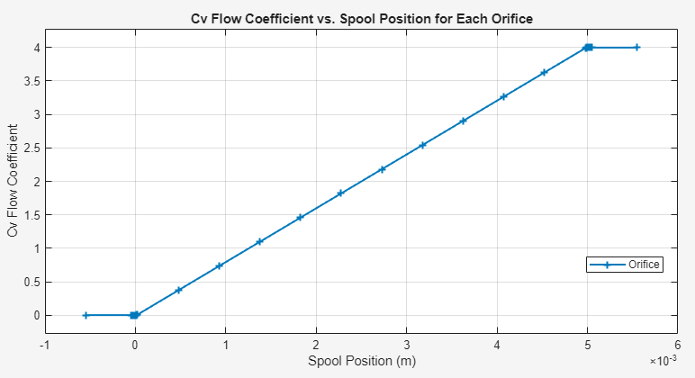
To generate a characteristic plot of the valve, click the Plot button next to Valve characteristics. The plot shows the sonic conductance, Kv flow coefficient, Cv flow coefficient, or orifice area as a function of spool position.
To update the data after changing the block parameters, click Reload Data in the figure window.
This figure shows the valve configuration with default values.
Assumptions and Limitations
The
Sonic conductancesetting of the Valve parameterization parameter is for pneumatic applications. If you use this setting for moist air with high levels of trace gasses or are modeling a fluid other than air, you may need to scale the sonic conductance by the square root of the mixture specific gravity.This block does not model supersonic flow.
There is no heat exchange between the valve and the environment.
Ports
Conserving
Input
Parameters
References
[1] ISO 6358-3. "Pneumatic fluid power – Determination of flow-rate characteristics of components using compressible fluids – Part 3: Method for calculating steady-state flow rate characteristics of systems". 2014.
[2] IEC 60534-2-3. "Industrial-process control valves – Part 2-3: Flow capacity – Test procedures". 2015.
[3] ANSI/ISA-75.01.01. "Industrial-Process Control Valves – Part 2-1: Flow capacity – Sizing equations for fluid flow underinstalled conditions". 2012.
[4] P. Beater. Pneumatic Drives. Springer-Verlag Berlin Heidelberg. 2007.
Extended Capabilities
Version History
Introduced in R2025a