Generate DPI Component Using MATLAB
Create MATLAB Function and Testbench
Create MATLAB Function
Code the MATLAB® function you want to export to a SystemVerilog environment. For information about coding MATLAB functions, see "Function Basics" in the MATLAB documentation.
Consider adding the compilation directive %#codegen to your
function. This directive can help you diagnose and fix violations that would
result in errors during code generation. See Compilation Directive %#codegen (MATLAB Coder).
While you code your function, keep in mind the Limitations, which describe the various aspects of DPI component generation that you must know. These aspects include which data types are valid, what files are generated, and how the shared libraries are compiled.
In this example, the MATLAB function fun.m takes a single input and
multiplies it by 2. The function includes the compilation directive
%#codegen.
function y = fun(x)
%#codegen
y = x * 2;
The process of creating the MATLAB includes writing the code, creating the testbench, and running the testbench in an iterative process. When you are satisfied that your function does what you intend it to do, continue on to Generate SystemVerilog DPI Component.
Create Testbench
Create a testbench to exercise the function. In this example, the testbench
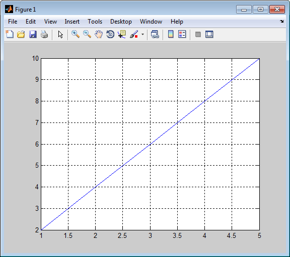
applies a test vector against fun.m and plots the
output.
function sample=fun_tb
% Testbench should not require input, however you can give an output.

% Define a test vector
tVecIn = [1,2,3,4,5];

% Exercise fun.m and plot results to make sure function is working correctly
tVecOut = arrayfun(@(in) fun(in),tVecIn);
plot(tVecIn,tVecOut);
grid on;

% Get my sample input to use it with function dpigen.
sample = tVecIn(1);
Note that a testbench should not have inputs. The testbench can load test vectors using MAT files or any other data file, so it does not require inputs.
The output of fun_tb, sample, is going
to be used as the function inputs argument for fun.m during
the call to dpigen, which is why it is a single element.
See Generate SystemVerilog DPI Component.
Run Testbench
fun_tb
ans =

     1
Next, generate the SystemVerilog DPI component. See Generate SystemVerilog DPI Component.
Generate SystemVerilog DPI Component
Generate DPI Component with dpigen Function
Use the function dpigen to generate the DPI
component. This function has several optional input arguments. At a minimum,
specify the MATLAB function you want to generate a component for and the function
inputs. If you also want to generate a testbench to exercise the generated
component, use the -testbench option.
dpigen func -args input_arg -testbench test_bench_name
Define the inputs as required by the function. In this example,
sampleis a scalar value of type double.sample = 1;
Call the DPI component generator function:
dpigen fun -args sample -testbench fun_tb
The command, issued as shown, performs the following tasks:
Generates
fun_dpi.sv– a SystemVerilog component for the functionfun.m.The function inputs forfun.mare specified in sample.Generates
fun_dpi_pkg.sv– a SystemVerilog package file. This file contains all the imported function declarations.Creates a testbench for the generated component.
For this call to
dpigen, MATLAB outputs the following messages:### Generating DPI Wrapper fun_dpi.c ### Generating DPI Wrapper header file fun_dpi.h ### Generating SystemVerilog module package fun_dpi_pkg.sv ### Generating SystemVerilog module fun_dpi.sv ### Generating makefiles for: fun_dpi ### Compiling the DPI Component ### Generating SystemVerilog testbench fun_tb.sv ### Generating testbench simulation script for Siemens Questa/ModelSim run_tb_mq.do ### Generating testbench simulation script for Cadence Incisive run_tb_incisive.sh ### Generating testbench simulation script for Cadence Xcelium run_tb_xcelium.sh ### Generating testbench simulation script for Synopsys VCS run_tb_vcs.sh ### Generating testbench simulation script for Vivado Simulator run_tb_vivado.bat
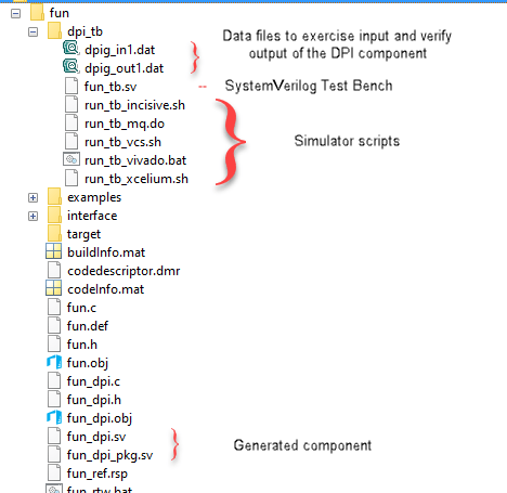
The function shown in the previous example generates the following folders and files:

Examine Generated Package File
Examine the generated package file. Note the declarations of the
initialize, reset,
terminate, and fun functions.
This example shows the code generated for
fun_dpi_pkg.sv.
// File: C:\fun_example\codegen\dll\fun\fun_dpi_pkg.sv
// Created: 2017-12-19 09:18:00
// Generated by MATLAB 9.5 and HDL Verifier 5.4

`timescale 1ns / 1ns
package fun_dpi_pkg;

// Declare imported C functions
import "DPI" function chandle DPI_fun_initialize(input chandle existhandle);
import "DPI" function chandle DPI_fun_reset(input chandle objhandle,input real x,output real y);
import "DPI" function void DPI_fun(input chandle objhandle,input real x,output real y);


import "DPI" function void DPI_fun_terminate(input chandle existhandle);

endpackage : fun_dpi_pkg
Examine Generated Component
Examine the generated component so that you can understand how the
dpigen function converted MATLAB code to SystemVerilog code. For more information on what the
function includes, see Generated SystemVerilog Wrapper.
This example shows the code generated for
fun_dpi.sv.
// File: C:\fun_example\codegen\dll\fun\fun_dpi.sv
// Created: 2017-12-19 09:18:00
// Generated by MATLAB 9.5 and HDL Verifier 5.4

`timescale 1ns / 1ns

import fun_dpi_pkg::*;

module fun_dpi(
    input bit clk,
    input bit clk_enable,
    input bit reset,
    input real x,
    output real y
);

    chandle objhandle=null;
    real y_temp;

    initial begin
        objhandle=DPI_fun_initialize(objhandle);
    end

    final begin
        DPI_fun_terminate(objhandle);
    end

    always @(posedge clk or posedge reset) begin
        if(reset== 1'b1) begin
            objhandle=DPI_fun_reset(objhandle,x,y_temp);
            y<=y_temp;
        end
        else if(clk_enable) begin
            DPI_fun(objhandle,x,y_temp);
            y<=y_temp;
        end
    end
endmodule
Examine Generated Testbench
Examine the generated testbench so you can see how function
dpigen created this testbench from the MATLAB code. For more information on the generated testbench, see Generated Testbench.
This example shows the code generated for fun_tb.sv.
// File: C:\fun_example\codegen\dll\fun\dpi_tb\fun_tb.sv
// Created: 2017-12-19 09:18:13
// Generated by MATLAB 9.5 and HDL Verifier 5.4

`timescale 1ns / 1ns
module fun_tb;
    real x;
    real y_ref;
    real y_read;
    real y;
    // File Handles
    integer fid_x;
    integer fid_y;
    // Other testbench variables
    bit clk;
    bit clk_enable;
    bit reset;
    integer fscanf_status;
    reg testFailure;
    reg tbDone;
    bit[63:0] real_bit64;
    bit[31:0] shortreal_bit64;
    parameter CLOCK_PERIOD= 10;
    parameter CLOCK_HOLD= 2;
    parameter RESET_LEN= 2*CLOCK_PERIOD+CLOCK_HOLD;
    // Initialize variables
    initial begin
        clk = 1;
        clk_enable = 0;
        testFailure = 0;
        tbDone = 0;
        reset = 1;
        fid_x = $fopen("dpig_in1.dat","r");
        fid_y = $fopen("dpig_out1.dat","r");
        // Initialize multirate counters
        #RESET_LEN reset = 0;
    end
    // Clock
    always #(CLOCK_PERIOD/2) clk = ~ clk;
    always@(posedge clk) begin
        if (reset == 0) begin
            #CLOCK_HOLD
            clk_enable <= 1;
            fscanf_status = $fscanf(fid_x, "%h", real_bit64);
            x = $bitstoreal(real_bit64);
            if ($feof(fid_x))
                tbDone = 1;
            fscanf_status = $fscanf(fid_y, "%h", real_bit64);
            y_read = $bitstoreal(real_bit64);
            if ($feof(fid_y))
                tbDone = 1;
            y_ref <= y_read;
            if (clk_enable == 1) begin
                assert ( ((y_ref - y) < 2.22045e-16) && ((y_ref - y) > -2.22045e-16) ) else begin
                    testFailure = 1;
                    $display("ERROR in output y_ref at time %0t :", $time);
                    $display("Expected %e; Actual %e; Difference %e", y_ref, y, y_ref-y);
                end
                if (tbDone == 1) begin
                    if (testFailure == 0)
                        $display("**************TEST COMPLETED (PASSED)**************");
                    else
                        $display("**************TEST COMPLETED (FAILED)**************");
                    $finish;
                end
            end
        end
    end

    // Instantiate DUT
    fun_dpi u_fun_dpi(
    .clk(clk),
    .clk_enable(clk_enable),
    .reset(reset),
    .x(x),
    .y(y)
    );
endmodule
Next, run the generated testbench in the HDL simulator. See Run Generated Testbench in HDL Simulator. If you plan to port the component and optional testbench from Windows® to Linux®, see Port Generated Component and Testbench to Linux.
Run Generated Testbench in HDL Simulator
This section includes instructions for running the generated testbench in one of the supported HDL simulators: Siemens® ModelSim™ and Questa™, Cadence® Xcelium™, and Synopsys® VCS®. It is possible that this code will work in other (unsupported) HDL simulators but it is not guaranteed.
Choose the workflow for your HDL simulator.
Run Testbench in ModelSim and Questa Simulators
Start ModelSim or Questa in GUI mode.
Change your current directory to the
dpi_tbfolder under the code generation directory in MATLAB.Enter the following command in the shell to start your simulation:
do run_tb_mq.doThis generated script contains the name of the component and testbench, and instructions to the HDL simulator for running the testbench.
When the simulation finishes, you should see the following text displayed in your console:
**************TEST COMPLETED (PASSED)**************
This message tells you that the testbench was run against the generated component successfully.
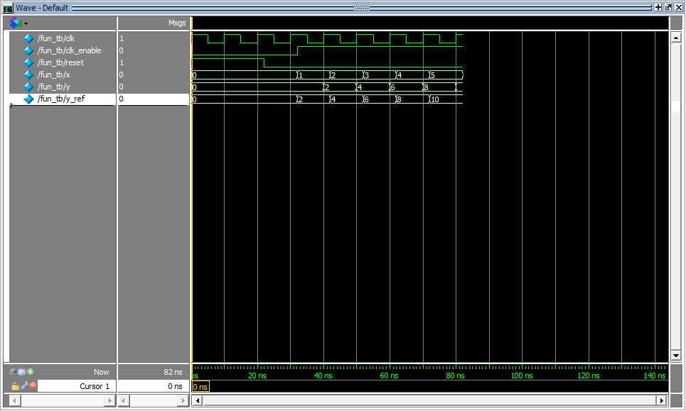
The following wave form image from this example demonstrates that the generated testbench was successfully exercised in the HDL simulator.

Next, import your component. See Use Generated DPI Functions in SystemVerilog.
Run Testbench in Xcelium Simulator
Launch Xcelium.
Start your terminal shell.
Change the current directory to
dpi_tbunder the code generation directory in MATLAB.Enter the following command in the shell to start the simulation:
sh run_tb_xcelium.shThis generated script contains the name of the component and testbench, and instructions to the HDL simulator for running the testbench.
When the simulation finishes, you should see the following text displayed in your console:
**************TEST COMPLETED (PASSED)**************
This message tells you that the testbench was run against the generated component successfully.
Run Testbench in VCS Simulator
Launch VCS.
Start your terminal shell.
Change the current directory to
dpi_tbunder the code generation directory in MATLAB.Enter the following command in your shell to start the simulation:
sh run_tb_vcs.shThis generated script contains the name of the component and testbench, and instructions to the HDL simulator for running the testbench.
When the simulation finishes, you should see the following text displayed in your console:
**************TEST COMPLETED (PASSED)**************
This message tells you that the testbench was run against the generated component successfully.
Use Generated DPI Functions in SystemVerilog
To use the generated DPI component in a SystemVerilog testbench, first you must include the package file in your SystemVerilog environment. This will have the DPI functions available within the scope of your SystemVerilog module. Then, you must call the generated functions. When you compile the SystemVerilog code that contains the imported generated functions, use a DPI-aware SystemVerilog compiler and specify the component and package file names along with the SystemVerilog code.
The following example demonstrates adding the generated DPI component for
fun.m to a SystemVerilog module.
Call the
Initializefunction.DPI_fun_initialize();
Call the function generated from
fun.m.DPI_fun(x,y);
You can now modify the generated code as needed.
Example
module test_twofun_tb;

	initial begin
		DPI_fun_initialize();
	end

	always@(posedge clk) begin
		#1
		DPI_fun(x,y);
	end
Port Generated Component and Testbench to Linux
To port the component and optional testbench from a Windows operating system to a Linux operating system, follow one of these workflows based on your HDL simulator.
Note
You must have an Embedded Coder® license for porting your component from Windows to Linux.
Generate Generic DPI Component
Follow this workflow for all of the supported HDL simulators. The software supports the Siemens ModelSim and Questa, Cadence Xcelium, and Synopsys VCS simulators. You generate the DPI component generic to all the supported HDL simulators.
Tasks on Windows Host Machine
Create a
coder.config(MATLAB Coder) object. Change the target HW device type toLP64for the Linux operating system.cfg=coder.config('dll');cfg.HardwareImplementation.TargetHWDeviceType='Generic->64-bit Embedded Processor (LP64)';
Run the
dpigenfunction using the option-configto use theconfigobject that you created in step 1. Use the option-cso that thedpigenfunction generates only code.dpigen -config cfg DataTypes.m -args InputSample -c
Generate a zip archive to port to Linux, navigate to the source folder that contains the
buildInfofile, and execute these commands at the MATLAB command prompt:load buildInfo packNGo(buildInfo)
Navigate to the top-level folder. Find the ZIP archive that you generate in step 3, which has the same name as the MATLAB function. Copy the ZIP archive to the Linux machine.
Tasks on Linux Target Machine
Unzip the file using the
-joption to extract all the files with a flattened folder structure. You can unzip the contents into any folder.unzip -j DataTypes.zip
Copy this generic makefile script into an empty file:
SRC=$(wildcard *.c)
OBJ=$(SRC:.c=.o)

SHARE_LIB_NAME=DPI_Component.so

all: $(SRC) $(SHARE_LIB_NAME)
	@echo "### Successfully generated all binary outputs."

$(SHARE_LIB_NAME): $(OBJ)
	gcc -shared -lm $(OBJ) -o $@

.c.o:
	gcc -c -fPIC -Wall -pedantic -Wno-long-long -fwrapv -O0 $< -o $@
Replace
DPI_Component.sowith the name of the shared library you want to create.Save the script as
Porting_DPIC.mkin the folder that contains the zip files.
Build the shared library.
make -f Porting_DPIC.mk all
To use the generated component with SystemVerilog, see Use Generated DPI Functions in SystemVerilog.
(Optional) Run the testbench that the software generated in Windows.
Copy the contents of the
dpi_tbfolder from the Windows host machine to the Linux target machine.Run the testbench.
To run the testbench in an HDL simulator, see Run Generated Testbench in HDL Simulator.
Generate Simulator-Specific DPI Component
Follow this workflow for the Siemens ModelSim and Questa, Cadence Xcelium, Synopsys VCS, and AMD® Vivado® HDL simulators. You generate the DPI component for your chosen simulator.
Use this workflow for easier porting steps. If you use this workflow, you do not need to create a generic makefile script and build the shared library on the Linux target machine to use the generated component. If you generate a testbench to exercise the generated component, you do not need to copy the testbench folder from the Windows host machine to the Linux target machine separately.
Tasks on Windows Host Machine
Create a
coder.config(MATLAB Coder) object.cfg=coder.config('dll');Select the target simulator and operating system by configuring the
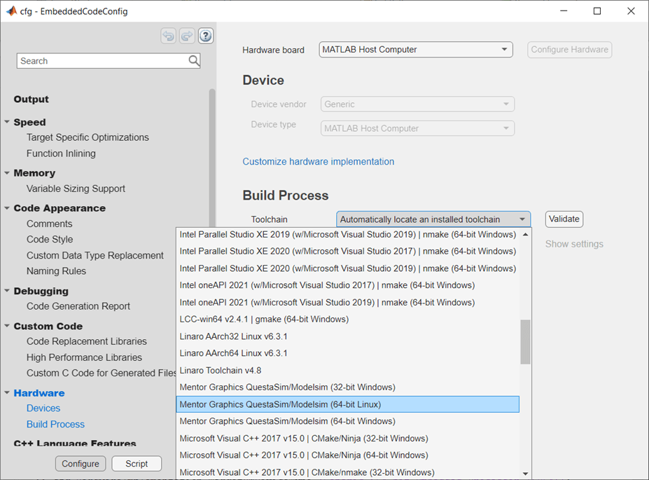
coder.configobject that you created in step 1. In the MATLAB workspace, double-clickcfgto open the EmbeddedCodeConfig dialog forcfg. On the Hardware pane, under Build Process, select a target Toolchain. This option specifies the target simulator and operating system where you run simulations. The supported cross-product toolchains are:Cadence Xcelium (64-bit Linux)Siemens Questa/ModelSim (64-bit Linux)Synopsys VCS (64-bit Linux)AMD Vivado Simulator (64-bit Linux)

Run the
dpigenfunction using the-configoption to use theconfigobject. Use the-testbenchoption if you also want to generate a testbench to exercise the generated component. Use the-coption so that thedpigenfunction generates only code.dpigen -config cfg DataTypes.m -args InputSample -testbench DataTypes_tb.m -c
Generate a ZIP archive to port to Linux, navigate to the source folder, which contains the
buildInfofile.load buildInfo
Use the
packNGo(MATLAB Coder) function to package the generated files and any required dependencies before copying them to the target machine. Specify the argument'minimalHeaders',falseto include all the header files on the include path in the ZIP archive.packNGo(buildInfo,'minimalHeaders',false)
Navigate to the top-level folder. Find the ZIP archive that you generate in step 3, which has the same name as the MATLAB function. Copy the ZIP archive to the Linux machine. The ZIP archive contains the ModelSim file with the
.doextension or the Xcelium, VCS, or Vivado file with the.shextension.
Tasks on Linux Target Machine
Unzip the file into a folder of your choice.
unzip DataTypes.zip
Start the HDL simulator.
Navigate to the folder that contains the generated files that you unzipped in step 1.
VCS simulator only: Set up the simulator environment path. Use your own Synopsys VCS installation path when executing the command.
Here,set VCS_HOME = C:/Synopsys/temp/vcs/S-2021.09-1
VCS_HOMEis the name of the environment variable.Build the project and run the testbench in the HDL simulator.
For the ModelSim and Questa simulators, run these commands.
do DataTypes.do
do run_tb_mq.do
For the Xcelium, VCS, and Vivado simulators, run these commands. Replace
simulatorsh DataTypes.sh sh run_tb_simulator.sh %Replace
simulator
Limitations
For the VCS and Vivado simulators, the cross-platform DPI generation does not support variable-sized vectors.
For the Vivado simulator, the DPI component generation does not support
singleanddoubledata types.You cannot set up third-party tools in MATLAB Online™, so you cannot use these features in MATLAB Online:
Testbench execution for DPI generation
Use of EDA toolchains for compiling DPI shared libraries