Test the Generated Code
There are different ways to test the generated code at different steps throughout the development process so you can find and address failures early. Testing methods include:
Model testing
Software-in-the-loop (SIL) testing
Processor-in-the-loop (PIL) testing
Hardware-in-the-loop (HIL) testing
This example shows how to compare the numerical behavior of the generated code to the behavior of the model by performing simulation testing and SIL testing back-to-back. The basic workflow for back-to-back testing is:
Configure the model hierarchy for testing.
Set up a harness model that references the component model.
Run the normal and SIL simulations back-to-back.
Examine the test results and address failures.
You can use other tools available with Simulink to perform other types of testing and to manage your testing workflows.
Set Up the Testing Configuration
First, configure the component and subcomponent models for
back-to-back testing. Use the shared configuration
ControllerConfigCoverage from the data dictionary.
If you have not already done so, follow the steps in the previous part of the workflow, Optimize the Generated Code, or run the script.
openExample("EvPowertrainController")
TestConfigEvPowertrain
From the model
EvPowertrainController, on the Modeling tab, open the Model Explorer.Navigate to the EvPowertrainController > External Data > evModelingData > Configurations node.
In the center pane, select the configuration reference
ActiveSharedReference. On the right pane, from the Name drop-down list, selectControllerConfigTestingand click Apply.This deployment configuration is the same as the previous configuration that you edited, except for these parameter settings:
Measure task execution time — off
Measure task stack usage — off
Code coverage for SIL or PIL > Third-party tool —
None (use Simulink
                                                  Coverage)
or select a third-party coverage analysis tool.
If you have Simulink® Coverage™, you can collect code coverage metrics by setting parameters on the Coverage pane. For this example, select Enable coverage analysis and set Structural coverage level to
Modified Condition Decision Coverage (MCDC).Click Apply.
In the left pane of the Model Explorer, right-click the data dictionary
evModelingDataand click Save Changes.
Now, the models that refer to the shared configuration reference use the testing configuration.
Set Up a Harness Model for Testing
This example uses a harness model to load the test data and input it to the component model. By using a harness model for testing, you can:
Model the external environment of the component by using a plant model.
Separate the testing simulation environment from the model under development.
Perform unit testing by using a different harness model for each level of the model hierarchy that you want to test.
The harness model for this example
(EvPowertrainHarness) was set up in the
section Set Up a Harness Model or by the script
TestConfigEvPowertrain.
Simulink Test Harnesses
If you have Simulink Test™, instead of using a separate harness model, you can use test harnesses stored in the model to:
Create a test-specific simulation environment that is stored in the model file.
Isolate individual blocks in the model for unit testing.
Add inputs, verification logic, dashboard blocks, and physical plant models to the test harness.
Test potential design changes in the test harness before changing the production model.
For more information, see Create or Import Test Harnesses and Select Properties (Simulink Test) and Manage Test Harnesses (Simulink Test).
Run Back-to-Back Normal and SIL Simulations
From the harness model, run the back-to-back simulations.
From the harness model
EvPowertrainHarness, open the SIL/PIL Manager app.On the SIL/PIL tab, set these SIL simulation settings:
Mode — Automated Verification
System Under Test — Model blocks in SIL/PIL mode
Top Model Mode — Normal
Settings > Task Profiling — off
Settings > Functions — off
Settings > Coverage Collection — on
Settings > Coverage Settings — Referenced Models
Click Run Verification. First, the model simulates in normal mode and collects results. Then, the harness runs the models in SIL mode by executing the associated generated code and collects results.
Examine Test Results
By default, the SIL/PIL Manager app compares the results from the normal and SIL simulations and displays them in the Data Inspector. By testing the generated code against the model, you can confirm that they are functionally equivalent.
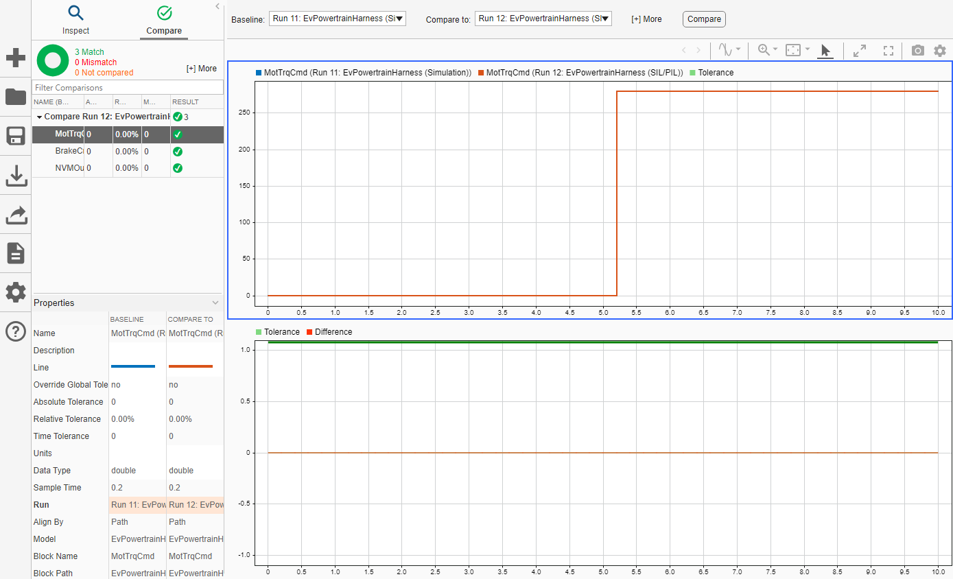
For the example, the results for the two simulations match. For production code, you would create and run additional tests.
If you collected coverage metrics, you can view the results in the model canvas, the Code view, and in the coverage report. For more information, see Analyze Code and Perform Software-in-the-Loop Testing (Simulink Coverage).
Simulink Test Manager
If you have Simulink Test, you can use Simulink Test Manager to:
Create test cases for Simulink models.
Run SIL, PIL, and HIL tests.
Group tests into test suites and test files.
Link test cases to design requirements.
For more information, see:
Simulink Test Manager (Simulink Test)
Generate Tests and Test Harnesses for a Model or Components (Simulink Test)
View Test Case Results (Simulink Test)
Additional Testing Methods
This example showed you how to test the numerical equivalence of the model and generated code by running back-to-back normal and SIL simulations. To test your production models and generated code, consider these additional testing methods for different stages in your model-based design workflow.
Processor-in-the-Loop (PIL) Testing
A processor-in-the-loop (PIL) simulation cross-compiles generated source code, and then downloads and runs object code on your target hardware. Similar to a SIL simulation, PIL simulation enables you to test whether the model and generated code are numerically equivalent. For more information, see SIL and PIL Simulations and Configure and Run PIL Simulation.
Hardware-in-the-Loop (HIL) Testing
You can test your generated code on your target hardware by using the Run on Custom Hardware app to:
Validate component functionality on production hardware.
Evaluate performance of the generated code on the production hardware.
Monitor signals and tune parameters while the target application runs on hardware.
For more information, see External Mode Simulations for Parameter Tuning, Signal Monitoring, and Code Execution Profiling and Run on Custom Hardware.
Alternatively, you can manually integrate and deploy the generated code for testing on target hardware. For more information, see Component Verification in Target Environment.
Tools Qualification and Certification
You can use the IEC Certification Kit (for ISO 26262 and IEC 61508) to qualify Embedded Coder® for supported industry standards, including ISO 26262: 2018, IEC 61508: 2010, IEC 62304: 2015, ISO 25119: 2018, and EN 50128: 2011. For more information, see Tool Certification (IEC Certification Kit) and Overview of the Artifacts in the IEC Certification Kit (IEC Certification Kit).
Continuous Integration (CI)
To manage your development process automatically, you can integrate your modeling and code generation workflows with a continuous integration (CI) system. CI enables you to:
Integrate changes into a shared repository throughout your development workflow.
Automate and standardize building code, testing, and packaging.
For more information, see Develop and Integrate Software with Continuous Integration and Continuous Integration for Verification of Simulink Models.
If you have Simulink Test, you can connect test results to continuous integration systems, as shown in Output Results for Continuous Integration Systems (Simulink Test).