Radar Detection Generator
Create detection objects from radar measurements
Radar Detection Generator is not recommended unless you require C/C++ code generation. Use Driving Radar Data Generator instead. For more information, see Version History.
Libraries:
Automated Driving Toolbox /
Driving Scenario and Sensor Modeling
Description
The Radar Detection Generator block generates detections from radar measurements taken by a radar sensor mounted on an ego vehicle. Detections are derived from simulated actor poses and are generated at intervals equal to the sensor update interval. By default, detections are referenced to the coordinate system of the ego vehicle. The generator can simulate real detections with added random noise and also generate false alarm detections. A statistical model generates the measurement noise, true detections, and false positives. The random numbers generated by the statistical model are controlled by random number generator settings on the Measurements tab. You can use the Radar Detection Generator to create input to a Multi-Object Tracker block. When building scenarios and sensor models using the Driving Scenario Designer app, the radar sensors exported to Simulink® are output as Radar Detection Generator blocks.
Ports
Input
Scenario actor poses in ego vehicle coordinates, specified as a Simulink bus containing a MATLAB structure.
The structure must contain these fields.
| Field | Description | Type |
|---|---|---|
NumActors | Number of actors | Nonnegative integer |
Time | Current simulation time | Real-valued scalar |
Actors | Actor poses | NumActors-length array of actor pose structures |
Each actor pose structure in Actors must contain
these fields.
| Field | Description |
|---|---|
ActorID | Scenario-defined actor identifier, specified as a positive integer. |
Position | Position of actor, specified as a real-valued vector of the form [x y z]. Units are in meters. |
Velocity | Velocity (v) of actor in the x- y-, and z-directions, specified as a real-valued vector of the form [vx vy vz]. Units are in meters per second. |
Roll | Roll angle of actor, specified as a real-valued scalar. Units are in degrees. |
Pitch | Pitch angle of actor, specified as a real-valued scalar. Units are in degrees. |
Yaw | Yaw angle of actor, specified as a real-valued scalar. Units are in degrees. |
AngularVelocity | Angular velocity (ω) of actor in the x-, y-, and z-directions, specified as a real-valued vector of the form [ωx ωy ωz]. Units are in degrees per second. |
Output
Object detections, returned as a Simulink bus containing a MATLAB structure. For more details about buses, see Create Nonvirtual Buses (Simulink).
You can pass object detections from these sensors and other sensors to a tracker, such as a Multi-Object Tracker block, and generate tracks.
| Field | Description | Type |
|---|---|---|
NumDetections | Number of detections | integer |
IsValidTime | False when updates are requested at times that are between block invocation intervals | Boolean |
Detections | Object detections | Array of object detection structures of length set by
the Maximum number of reported
detections parameter. Only
NumDetections of these are actual
detections. |
Each object detection structure contains these properties.
| Property | Definition |
|---|---|
Time | Measurement time |
Measurement | Object measurements |
MeasurementNoise | Measurement noise covariance matrix |
SensorIndex | Unique ID of the sensor |
ObjectClassID | Object classification |
MeasurementParameters | Parameters used by initialization functions of nonlinear Kalman tracking filters |
ObjectAttributes | Additional information passed to tracker |
For Cartesian coordinates,
MeasurementandMeasurementNoiseare reported in the coordinate system specified by the Coordinate system used to report detections parameter.For spherical coordinates,
MeasurementandMeasurementNoiseare reported in the spherical coordinate system based on the sensor Cartesian coordinate system.
Measurement and Measurement Noise
| Coordinate System Used to Report Detections | Measurement and Measurement Noise Coordinates | |||||||||||||||
|---|---|---|---|---|---|---|---|---|---|---|---|---|---|---|---|---|
'Ego Cartesian' |
Coordinate dependence on Enable range rate measurements
| |||||||||||||||
'Sensor Cartesian' | ||||||||||||||||
'Sensor spherical' |
Coordinate dependence on Enable elevation angle measurements and Enable range rate measurements
|
MeasurementParameters
| Parameter | Definition |
|---|---|
Frame | Enumerated type indicating the frame used to
report measurements. When Frame
is set to 'rectangular',
detections are reported in Cartesian coordinates.
When Frame is set
'spherical', detections are
reported in spherical coordinates. |
OriginPosition | 3-D vector offset of the sensor origin from the
ego vehicle origin. The vector is derived from the
SensorLocation and
Height properties specified
in the radarDetectionGenerator. |
Orientation | Orientation of the radar sensor coordinate system
with respect to the ego vehicle coordinate system.
The orientation is derived from the
Yaw,
Pitch, and
Roll properties of the
radarDetectionGenerator. |
HasVelocity | Indicates whether measurements contain velocity or range rate components. |
HasElevation | Indicates whether measurements contain elevation components. |
The ObjectAttributes property of each detection
is a structure with these fields.
| Field | Definition |
|---|---|
TargetIndex | Identifier of the actor,
ActorID, that generated the
detection. For false alarms, this value is
negative. |
SNR | Signal-to-noise ratio of the detection. Units are in dB. |
Parameters
Parameters
Sensor Identification
Unique sensor identifier, specified as a positive integer. The sensor identifier distinguishes detections that come from different sensors in a multisensor system. If a model contains multiple sensor blocks with the same sensor identifier, the Bird's-Eye Scope displays an error.
Example: 5
Required time interval between sensor updates, specified as a positive real scalar. The value of this parameter must be an integer multiple of the Actors input port data interval. Updates requested from the sensor between update intervals contain no detections. Units are in seconds.
Sensor Extrinsics
Location of the radar sensor center, specified as a real-valued 1-by-2 vector. The Sensor's (x,y) position (m) and Sensor's height (m) parameters define the coordinates of the radar sensor with respect to the ego vehicle coordinate system. The default value corresponds to a radar mounted at the center of the front grill of a sedan. Units are in meters.
Radar sensor height above the ground plane, specified as a positive real scalar. The height is defined with respect to the vehicle ground plane. The Sensor's (x,y) position (m) and Sensor's height (m) parameters define the coordinates of the radar sensor with respect to the ego vehicle coordinate system. The default value corresponds to a radar mounted at the center of the front grill of a sedan. Units are in meters.
Example: 0.25
Yaw angle of radar sensor, specified as a real scalar. Yaw angle is the angle between the center line of the ego vehicle and the downrange axis of the radar sensor. A positive yaw angle corresponds to a clockwise rotation when looking in the positive direction of the z-axis of the ego vehicle coordinate system. Units are in degrees.
Example: -4.0
Pitch angle of sensor, specified as a real scalar. The pitch angle is the angle between the downrange axis of the radar sensor and the x-y plane of the ego vehicle coordinate system. A positive pitch angle corresponds to a clockwise rotation when looking in the positive direction of the y-axis of the ego vehicle coordinate system. Units are in degrees.
Example: 3.0
Roll angle of the radar sensor, specified as a real scalar. The roll angle is the angle of rotation of the downrange axis of the radar around the x-axis of the ego vehicle coordinate system. A positive roll angle corresponds to a clockwise rotation when looking in the positive direction of the x-axis of the coordinate system. Units are in degrees.
Port Settings
Source of output bus name, specified as Auto or
Property. If you choose Auto,
the block will automatically create a bus name. If you choose
Property, specify the bus name using the
Specify an output bus name parameter.
Example: Property
Name of output bus.
Dependencies
To enable this parameter, set the Source of output bus
name parameter to Property.
Detection Reporting
Maximum number of detections reported by the sensor, specified as a positive integer. Detections are reported in order of increasing distance from the sensor until the maximum number is reached.
Example: 100
Coordinate system of reported detections, specified as one of these values:
Ego Cartesian— Detections are reported in the ego vehicle Cartesian coordinate system.Sensor Cartesian— Detections are reported in the sensor Cartesian coordinate system.Sensor spherical— Detections are reported in a spherical coordinate system. This coordinate system is centered at the radar and aligned with the orientation of the radar on the ego vehicle.
Interpreted execution— Simulate the model using the MATLAB interpreter. This option shortens startup time. InInterpreted executionmode, you can debug the source code of the block.Code generation— Simulate the model using generated C/C++ code. The first time you run a simulation, Simulink generates C/C++ code for the block. The C code is reused for subsequent simulations as long as the model does not change. This option requires additional startup time.
Measurements
Accuracy Settings
Azimuth resolution of the radar, specified as a positive real scalar. The azimuth resolution defines the minimum separation in azimuth angle at which the radar can distinguish two targets. The azimuth resolution is typically the 3dB-downpoint in azimuth angle beamwidth of the radar. Units are in degrees.
Example: 6.5
Elevation resolution of the radar, specified as a positive real scalar. The elevation resolution defines the minimum separation in elevation angle at which the radar can distinguish two targets. The elevation resolution is typically the 3dB-downpoint in elevation angle beamwidth of the radar. Units are in degrees.
Example: 3.5
Dependencies
To enable this parameter, select the Enable elevation angle measurements check box.
Range resolution of the radar, specified as a positive real scalar. The range resolution defines the minimum separation in range at which the radar can distinguish between two targets. Units are in meters.
Example: 5.0
Range rate resolution of the radar, specified as a positive real scalar. The range rate resolution defines the minimum separation in range rate at which the radar can distinguish between two targets. Units are in meters per second.
Example: 0.75
Dependencies
To enable this parameter, select the Enable range rate measurements check box.
Bias Settings
Azimuth bias fraction of the radar, specified as a nonnegative real scalar. The azimuth bias is expressed as a fraction of the azimuth resolution specified in the Azimuthal resolution of radar (deg) parameter. Units are dimensionless.
Example: 0.3
Elevation bias fraction of the radar, specified as a nonnegative real scalar. The elevation bias is expressed as a fraction of the elevation resolution specified in the Elevation resolution of radar (deg) parameter. Units are dimensionless.
Example: 0.2
Dependencies
To enable this parameter, select the Enable elevation angle measurements check box.
Range bias fraction of the radar, specified as a nonnegative real scalar. Range bias is expressed as a fraction of the range resolution specified in the Range resolution of radar (m) parameter. Units are dimensionless.
Example: 0.15
Range rate bias fraction of the radar, specified as a nonnegative real scalar. Range rate bias is expressed as a fraction of the range rate resolution specified in Range rate resolution of radar (m) parameter. Units are dimensionless.
Example: 0.2
Dependencies
To enable this parameter, select the Enable range rate measurements check box.
Detector Settings
Field of view of radar sensor, specified as a real-valued 1-by-2
vector of positive values, [azfov elfov]. The field
of view defines the angular extent spanned by the sensor. Each component
must lie in the interval (0,180]. Targets outside of the field of view
of the radar are not detected. Units are in degrees.
Example: [14 7]
Maximum detection range, specified as a positive real scalar. The radar cannot detect a target beyond this range. Units are in meters.
Example: 250
Minimum and maximum detection range rates, specified as a real-valued 1-by-2 vector. The radar cannot detect a target outside of this range rate interval. Units are in meters per second.
Example: [-200 200]
Dependencies
To enable this parameter, select the Enable range rate measurements check box.
Probability of detecting a target, specified as a positive real scalar less than or equal to one. This quantity defines the probability of detecting target that has a radar cross-section specified by the Radar cross section at which detection probability is achieved (dBsm) parameter at the reference detection range specified by the Range where detection probability is achieved (m) parameter.
Example: 0.95
False alarm rate within a radar resolution cell, specified as a positive real scalar in the range [10–7, 10–3]. Units are dimensionless.
Example: 1e-5
Reference range for a given probability of detection, specified as a positive real scalar. The reference range is the range when a target having a radar cross-section specified by Radar cross section at which detection probability is achieved (dBsm) is detected with a probability of specified by Detection probability. Units are in meters.
Example: 150
Reference radar cross-section (RCS) for given probability of detection, specified as a nonnegative real scalar. The reference RCS is the value at which a target is detected with probability specified by Detection probability. Units are in dBsm.
Example: 2.0
Measurement Settings
Select this check box to model a radar that can measure target elevation angles.
Select this check box to model a radar that can measure target range rate.
Select this check box to add noise to radar sensor measurements.
Otherwise, the measurements are noise-free. The
MeasurementNoise property of each detection is
always computed and is not affected by the value you specify for the
Add noise to measurements parameter. By leaving
this check box off, you can pass the sensor's ground
truth measurements into a Multi-Object Tracker block.
Select this check box to enable reporting false alarm radar measurements. Otherwise, only actual detections are reported.
Select this parameter to enable line-of-sight occlusion, where the radar generates detections only from objects with a direct line of sight.
Random Number
                                    Generator Settings
Method to set the random number generator seed, specified as one of the options in the table.
| Option | Description |
|---|---|
Repeatable | The block generates a random initial seed
for the first simulation and reuses this seed for
all subsequent simulations. Select this parameter
to generate repeatable results from the
statistical sensor model. To change this initial
seed, at the MATLAB command prompt, enter:
|
Specify seed | Specify your own random initial seed for reproducible results by using the Specify seed parameter. |
Not repeatable | The block generates a new random initial seed after each simulation run. Select this parameter to generate nonrepeatable results from the statistical sensor model. |
Random number generator seed, specified as a nonnegative integer less than 232.
Example: 2001
Dependencies
To enable this parameter, set the Random Number
Generator Settings parameter to Specify
seed.
Actor Profiles
Method to specify actor profiles, which are the physical and radar characteristics of all actors in the driving scenario, specified as one of these options:
From Scenario Reader block— The block obtains the actor profiles from the scenario specified by the Scenario Reader block or RoadRunner Scenario Reader block.Parameters— The block obtains the actor profiles from the parameters that become enabled on the Actor Profiles tab.MATLAB expression— The block obtains the actor profiles from the MATLAB expression specified by the MATLAB expression for actor profiles parameter.
MATLAB expression for actor profiles, specified as a MATLAB structure, a MATLAB structure array, or a valid MATLAB expression that produces such a structure or structure array.
If your Scenario Reader block reads data from a drivingScenario object, to obtain the actor profiles directly from this
object, set this expression to call the actorProfiles function on the object. For example:
actorProfiles(scenario).
Example: struct('ClassID',5,'Length',5.0,'Width',2,'Height',2,'OriginOffset',[-1.55,0,0])
Dependencies
To enable this parameter, set the Select method to specify actor profiles parameter to MATLAB expression.
Scenario-defined actor identifier, specified as a positive integer or
length-L vector of unique positive integers.
L must equal the number of actors input into the
Actor input port. The vector elements must
match ActorID values of the actors. You can specify
Unique identifier for actors as
[]. In this case, the same actor profile
parameters apply to all actors.
Example: [1,2]
Dependencies
To enable this parameter, set the Select method to
specify actor profiles parameter to
Parameters.
User-defined classification identifier, specified as an integer or
length-L vector of integers. When
Unique identifier for actors is a vector, this
parameter is a vector of the same length with elements in one-to-one
correspondence to the actors in Unique identifier for
actors. When Unique identifier for
actors is empty, [], you must specify
this parameter as a single integer whose value applies to all
actors.
Example: 2
Dependencies
To enable this parameter, set the Select method to
specify actor profiles parameter to
Parameters.
Length of cuboid, specified as a positive real scalar or
length-L vector of positive values. When
Unique identifier for actors is a vector, this
parameter is a vector of the same length with elements in one-to-one
correspondence to the actors in Unique identifier for
actors. When Unique identifier for
actors is empty, [], you must specify
this parameter as a positive real scalar whose value applies to all
actors. Units are in meters.
Example: 6.3
Dependencies
To enable this parameter, set the Select method to
specify actor profiles parameter to
Parameters.
Width of cuboid, specified as a positive real scalar or
length-L vector of positive values. When
Unique identifier for actors is a vector, this
parameter is a vector of the same length with elements in one-to-one
correspondence to the actors in Unique identifier for
actors. When Unique identifier for
actors is empty, [], you must specify
this parameter as a positive real scalar whose value applies to all
actors. Units are in meters.
Example: 4.7
Dependencies
To enable this parameter, set the Select method to
specify actor profiles parameter to
Parameters.
Height of cuboid, specified as a positive real scalar or
length-L vector of positive values. When
Unique identifier for actors is a vector, this
parameter is a vector of the same length with elements in one-to-one
correspondence to the actors in Unique identifier for
actors. When Unique identifier for
actors is empty, [], you must specify
this parameter as a positive real scalar whose value applies to all
actors. Units are in meters.
Example: 2.0
Dependencies
To enable this parameter, set the Select method to
specify actor profiles parameter to
Parameters.
Rotational center of the actor, specified as a
length-L cell array of real-valued 1-by-3
vectors. Each vector represents the offset of the rotational center of
the actor from the bottom-center of the actor. For vehicles, the offset
corresponds to the point on the ground beneath the center of the rear
axle. When Unique identifier for actors is a
vector, this parameter is a cell array of vectors with cells in
one-to-one correspondence to the actors in Unique identifier
for actors. When Unique identifier for
actors is empty, [], you must specify
this parameter as a cell array of one element containing the offset
vector whose values apply to all actors. Units are in meters.
Example: [ -1.35, .2, .3 ]
Dependencies
To enable this parameter, set the Select method to
specify actor profiles parameter to
Parameters.
Radar cross-section (RCS) of actor, specified as a real-valued
Q-by-P matrix or
length-L cell array of real-valued
Q-by-P matrices.
Q is the number of elevation angles specified by
the corresponding cell in the Elevation angles defining
RCSPattern (deg) parameter. P is the
number of azimuth angles specified by the corresponding cell in
Azimuth angles defining RCSPattern (deg)
property. When Unique identifier for actors is a
vector, this parameter is a cell array of matrices with cells in
one-to-one correspondence to the actors in Unique identifier
for actors. Q and P
can vary in the cell array. When Unique identifier for
actors is empty, [], you must specify
this parameter as a cell array with one element containing a matrix
whose values apply to all actors. Units are in dBsm.
Example: [10 14 10; 9 13 9]
Dependencies
To enable this parameter, set the Select method to
specify actor profiles parameter to
Parameters.
Azimuth angles of radar cross-section pattern, specified as a
length-L cell array of real-valued
P-length vectors. Each vector represents the
azimuth angles of the P-columns of the radar cross
section specified in Radar cross section pattern
(dBsm). When Unique identifier for
actors is a vector, this parameter is a cell array of
vectors with cells in one-to-one correspondence to the actors in
Unique identifier for actors.
P can vary in the cell array. When
Unique identifier for actors is empty,
[], you must specify this parameter as a cell
array with one element containing a vector whose values apply to all
actors. Units are in degrees. Azimuth angles lie in the range -180° to
180° and must be in strictly increasing order.
When the radar cross sections specified in the cells of Radar cross section pattern (dBsm) all have the same dimensions, you need only specify a cell array with one element containing the azimuth angle vector.
Example: [-90:90]
Dependencies
To enable this parameter, set the Select method to
specify actor profiles parameter to
Parameters.
Elevation angles of radar cross-section pattern, specified as a
length-L cell array of real-valued
Q-length vectors. Each vector represent the
elevation angles of the Q-columns of the radar cross
section specified in Radar cross section pattern
(dBsm). When Unique identifier for
actors is a vector, this parameter is a cell array of
vectors with cells in one-to-one correspondence to the actors in
Unique identifier for actors.
Q can vary in the cell array. When
Unique identifier for actors is empty,
[], you must specify this parameter as a cell
array with one element containing a vector whose values apply to all
actors. Units are in degrees. Elevation angles lie in the range -90° to
90° and must be in strictly increasing order.
When the radar cross sections that are specified in the cells of Radar cross section pattern (dBsm) all have the same dimensions, you need only specify a cell array with one element containing an elevation angle vector.
Example: [-25:25]
Dependencies
To enable this parameter, set the Select method to
specify actor profiles parameter to
Parameters.
Extended Capabilities
C/C++ Code Generation
Generate C and C++ code using Simulink® Coder™.
Version History
Introduced in R2017bThe radarDetectionGenerator
System object™ and Radar Detection Generator block are not recommended
unless you require C/C++ code generation. Instead, use the drivingRadarDataGenerator
System object and Driving
Radar Data Generator, respectively. These new radar sensors provide
additional properties for modeling radar sensors, including the ability to generate
tracks and clustered detections.
There are no current plans to remove the radarDetectionGenerator System object or Radar Detection Generator block. MATLAB code and Simulink models that use these features will continue to run. You can still import radarDetectionGenerator objects into the Driving Scenario Designer app. However, the app updates the parameters of the imported sensor to reflect the parameters of a drivingRadarDataGenerator object. In addition, when you export a scenario containing a radarDetectionGenerator sensor to MATLAB code or to a Simulink model, the app exports the sensor as a drivingRadarDataGenerator object or Driving Radar Data Generator block, respectively.
In MATLAB code, replace all instances of radarDetectionGenerator with drivingRadarDataGenerator. In addition, update all radarDetectionGenerator properties with their equivalent drivingRadarDataGenerator properties, as shown in the table. The properties not listed in the table are either specific only to drivingRadarDataGenerator or identical in both objects.
radarDetectionGenerator Properties | Equivalent drivingRadarDataGenerator Properties |
|---|---|
|
|
|
|
|
|
| RangeLimits |
|
|
|
|
|
|
This table shows sample code for creating a drivingRadarDataGenerator object instead of a radarDetectionGenerator object.
| Discouraged Usage | Recommended Replacement |
|---|---|
radar = radarDetectionGenerator( ... 'SensorLocation',[-1 0], ... 'Height',0.2, ... 'Yaw',180, ... 'Pitch',0, ... 'Roll',0, ... 'MaxRange',50); | radar = drivingRadarDataGenerator( ... 'MountingLocation',[-1 0 0.2], ... 'MountingAngles',[180 0 0], ... 'RangeLimits',[0 50]); |
To generate detections from target poses at each simulation time step, replace the dets = radarDetectionGenerator(targets,time) syntax with dets = drivingRadarDataGenerator(targets,time).
In Simulink models, replace all Radar Detection Generator blocks with Driving Radar Data Generator blocks. In the Driving Radar Data Generator blocks, update the parameter values in the same way you would update the drivingRadarDataGenerator property values described in the Update Code section.
If your model contains a separate block that clusters detections, you can remove it because the Driving Radar Data Generator block clusters detections by default.
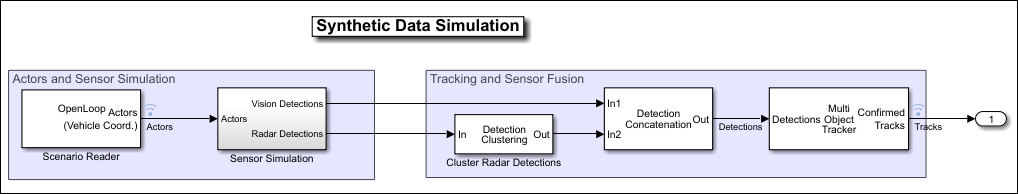
For example, in this model, the Sensor Simulation subsystem outputs concatenated detections from Radar Detection Generator blocks into a separate block that clusters the detections.
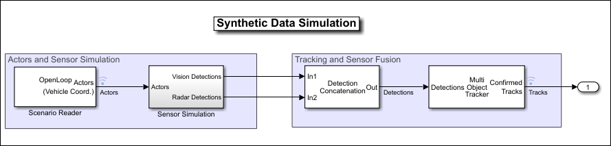
In this model, the Sensor Simulation subsystem outputs concatenated, clustered detections from Driving Radar Data Generator blocks directly into the next part of the model pipeline.
See Also
MATLAB Command
You clicked a link that corresponds to this MATLAB command:
Run the command by entering it in the MATLAB Command Window. Web browsers do not support MATLAB commands.
Select a Web Site
Choose a web site to get translated content where available and see local events and offers. Based on your location, we recommend that you select: .
You can also select a web site from the following list
How to Get Best Site Performance
Select the China site (in Chinese or English) for best site performance. Other MathWorks country sites are not optimized for visits from your location.
Americas
- América Latina (Español)
- Canada (English)
- United States (English)
Europe
- Belgium (English)
- Denmark (English)
- Deutschland (Deutsch)
- España (Español)
- Finland (English)
- France (Français)
- Ireland (English)
- Italia (Italiano)
- Luxembourg (English)
- Netherlands (English)
- Norway (English)
- Österreich (Deutsch)
- Portugal (English)
- Sweden (English)
- Switzerland
- United Kingdom (English)