gsmDownlinkConfig
Create GSM downlink TDMA frame configuration object
Description
The gsmDownlinkConfig object is a GSM downlink TDMA frame
configuration object. Use gsmDownlinkConfig objects to create GSM downlink
waveforms.
Creation
Syntax
Description
cfggsmdl = gsmDownlinkConfig
cfggsmdl = gsmDownlinkConfig(sps)SamplesPerSymbol property to
sps.
cfggsmdl = gsmDownlinkConfig(___,Name=Value)gsmDownlinkConfig(RiseTime=4) sets the burst rise time to
4 symbols. Specify name-value arguments after all other input
arguments.
Properties
Examples
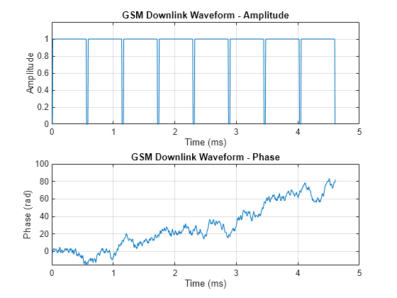
Create a GSM downlink TDMA frame configuration object with default settings, and then create a GSM waveform containing one TDMA frame. The GSM TDMA frame has eight time slots, each separated by a guard period of 8.25 symbols or about 30.46x10e-3 ms. Plot the GSM waveform.
Create a GSM downlink TDMA frame configuration object with default settings.
cfggsmdl = gsmDownlinkConfig
cfggsmdl =
  gsmDownlinkConfig with properties:

           BurstType: [NB    NB    NB    NB    NB    NB    NB    NB]
    SamplesPerSymbol: 16
                 TSC: [0 1 2 3 4 5 6 7]
         Attenuation: [0 0 0 0 0 0 0 0]
         PulseLength: 4
            RiseTime: 2
           RiseDelay: 0
            FallTime: 2
           FallDelay: 0
Display information about the configured gsmDownlinkConfig object by using the gsmInfo function. Assign the sample rate to a variable, Rs, for use in computing the plot timescale.
wfInfo = gsmInfo(cfggsmdl)
wfInfo = struct with fields:
              SymbolRate: 2.7083e+05
              SampleRate: 4.3333e+06
    BandwidthTimeProduct: 0.3000
    BurstLengthInSymbols: 156.2500
       NumBurstsPerFrame: 8
    BurstLengthInSamples: 2500
    FrameLengthInSamples: 20000
Rs = wfInfo.SampleRate;
Create the GSM waveform by using the gsmFrame function, and then plot the GSM waveform.
waveform = gsmFrame(cfggsmdl);

t = (0:length(waveform)-1)/Rs*1e3;
subplot(2,1,1)
plot(t,abs(waveform))
grid on
axis([0 5 0 1.2])
title('GSM Downlink Waveform - Amplitude')
xlabel('Time (ms)')
ylabel('Amplitude')
subplot(2,1,2)
plot(t,unwrap(angle(waveform)))
grid on
title('GSM Downlink Waveform - Phase')
xlabel('Time (ms)')
ylabel('Phase (rad)')

Create a GSM downlink TDMA frame configuration object that specifies 8 samples per symbol, and then create a GSM waveform containing one GSM downlink TDMA frame. The GSM TDMA frame are eight time slots, each separated by a guard period of 8.25 symbols or about 30.46x10e-3 ms separates each time slot. Plot the GSM waveform.
Create a GSM downlink TDMA frame configuration object, specifying 8 samples per symbols.
sps = 8;
cfggsmdl = gsmDownlinkConfig(sps)
cfggsmdl =
  gsmDownlinkConfig with properties:

           BurstType: [NB    NB    NB    NB    NB    NB    NB    NB]
    SamplesPerSymbol: 8
                 TSC: [0 1 2 3 4 5 6 7]
         Attenuation: [0 0 0 0 0 0 0 0]
         PulseLength: 4
            RiseTime: 2
           RiseDelay: 0
            FallTime: 2
           FallDelay: 0
Display information about the configured gsmDownlinkConfig object by using the gsmInfo function. Assign the sample rate to a variable, Rs, for use in computing the plot timescale.
wfInfo = gsmInfo(cfggsmdl)
wfInfo = struct with fields:
              SymbolRate: 2.7083e+05
              SampleRate: 2.1667e+06
    BandwidthTimeProduct: 0.3000
    BurstLengthInSymbols: 156.2500
       NumBurstsPerFrame: 8
    BurstLengthInSamples: 1250
    FrameLengthInSamples: 10000
Rs = wfInfo.SampleRate;
Create the GSM waveform by using the gsmFrame function, and then plot the GSM waveform.
waveform = gsmFrame(cfggsmdl);

t = (0:length(waveform)-1)/Rs*1e3;
subplot(2,1,1)
plot(t,abs(waveform))
grid on
axis([0 5 0 1.2])
title('GSM Downlink Waveform - Amplitude')
xlabel('Time (ms)')
ylabel('Amplitude')
subplot(2,1,2)
plot(t,unwrap(angle(waveform)))
grid on
title('GSM Downlink Waveform - Phase')
xlabel('Time (ms)')
ylabel('Phase (rad)')
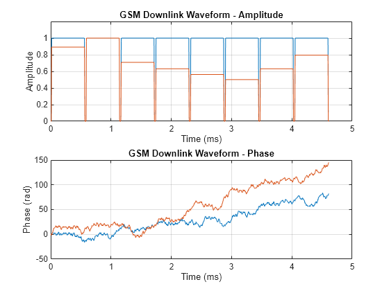
Create two GSM downlink TDMA frame configuration objects. Specify default settings for the first gsmDownlinkConfig object and adjust the signal power per time slot for the second. Generate GSM waveforms for both configurations. Plot the waveforms to show the signal attenuation per time slot in the second waveform.
Create a GSM downlink TDMA frame configuration object with default settings.
cfggsmdl = gsmDownlinkConfig
cfggsmdl =
  gsmDownlinkConfig with properties:

           BurstType: [NB    NB    NB    NB    NB    NB    NB    NB]
    SamplesPerSymbol: 16
                 TSC: [0 1 2 3 4 5 6 7]
         Attenuation: [0 0 0 0 0 0 0 0]
         PulseLength: 4
            RiseTime: 2
           RiseDelay: 0
            FallTime: 2
           FallDelay: 0
Create another GSM downlink TDMA frame configuration object, adjusting the signal attenuation settings per time slot.
cfggsmdl2 = gsmDownlinkConfig('Attenuation',[1 0 3 4 5 6 4 2])cfggsmdl2 =
gsmDownlinkConfig with properties:
BurstType: [NB NB NB NB NB NB NB NB]
SamplesPerSymbol: 16
TSC: [0 1 2 3 4 5 6 7]
Attenuation: [1 0 3 4 5 6 4 2]
PulseLength: 4
RiseTime: 2
RiseDelay: 0
FallTime: 2
FallDelay: 0
Display information about the configured gsmDownlinkConfig object by using the gsmInfo function. Assign the sample rate to a variable, Rs, for use in computing the plot timescale.
wfInfo = gsmInfo(cfggsmdl)
wfInfo = struct with fields:
              SymbolRate: 2.7083e+05
              SampleRate: 4.3333e+06
    BandwidthTimeProduct: 0.3000
    BurstLengthInSymbols: 156.2500
       NumBurstsPerFrame: 8
    BurstLengthInSamples: 2500
    FrameLengthInSamples: 20000
Rs = wfInfo.SampleRate;
Create the GSM waveforms, containing one TDMA frame, by using the gsmFrame function. GSM TDMA frames have are eight time slots, each separated by a guard period of 8.25 symbols or about 30.46x10e-3 ms separates each time slot. Plot each GSM waveform.
waveform = gsmFrame(cfggsmdl);
waveform2 = gsmFrame(cfggsmdl2);

t = (0:length(waveform)-1)/Rs*1e3;
subplot(2,1,1)
plot(t,[abs(waveform),abs(waveform2)])
grid on
axis([0 5 0 1.2])
title('GSM Downlink Waveform - Amplitude')
xlabel('Time (ms)')
ylabel('Amplitude')
subplot(2,1,2)
plot(t,[unwrap(angle(waveform)),unwrap(angle(waveform2))])
grid on
title('GSM Downlink Waveform - Phase')
xlabel('Time (ms)')
ylabel('Phase (rad)')
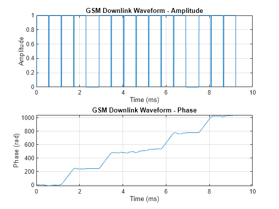
Generate and run a GSM waveform MEX function from the helper function createDownlinkWaveform. The createDownlinkWaveform helper function creates a GSM downlink waveform.
Write MATLAB Function
Open createDownlinkWaveform.m to see the code. The createDownlinkWaveform helper function generates a GSM downlink waveform by using the gsmDownlinkConfig object and the gsmInfo and gsmFrame functions.
Generate GSM Waveform
Use the createDownlinkWaveform helper function to create a GSM waveform containing two TDMA frames, and then plot the waveform.
[x,t] = createDownlinkWaveform(2);

figure
subplot(2,1,1);
plot(t,abs(x));
grid on;
title('GSM Downlink Waveform - Amplitude');
xlabel('Time (ms)');
ylabel('Amplitude')
subplot(2,1,2);
plot(t,unwrap(angle(x)));
grid on;
title('GSM Downlink Waveform - Phase');
xlabel('Time (ms)');
ylabel('Phase (rad)')
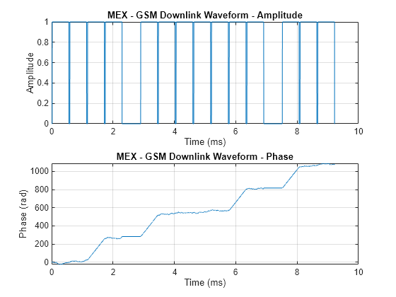
Generate MEX Function
Code generation defaults to MEX code generation when you do not specify a build target. By default, codegen names the generated MEX function createDownlinkWaveform_mex. Generate a MEX function from the createDownlinkWaveform helper function, and then run the MEX function to create two TDMA frames.
codegen createDownlinkWaveform -args 3
Code generation successful.
Generate Waveform Using MEX Function
Run the MEX function and plot the results. Since the waveform is created using random data, the phase plot changes each time you run the generateDownlinkFrame helper function or createDownlinkWaveform_mex function.
[x,t] = createDownlinkWaveform_mex(2);

figure
subplot(2,1,1);
plot(t,abs(x));
grid on;
title('MEX - GSM Downlink Waveform - Amplitude');
xlabel('Time (ms)');
ylabel('Amplitude')
subplot(2,1,2);
plot(t,unwrap(angle(x)));
grid on;
title('MEX - GSM Downlink Waveform - Phase');
xlabel('Time (ms)');
ylabel('Phase (rad)')
Model a GSM waveform generator in Simulink® by using the MATLAB® Function block and Communications Toolbox™ functions.
GSM Downlink Waveform Generation
The MATLAB Function (Simulink) block contains the gsmDownlinkWaveform function code. The code in the MATLAB Function block creates a GSM waveform by using the gsmDownlinkConfig object and the gsmFrame function.
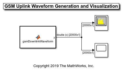
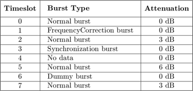
The gsmDownlinkConfig object specifies 16 samples per symbol and the time slot configuration for the GSM downlink TDMA frame shown is this table.
The output waveform has 16 samples for each GMSK symbol. The gsmFrame function generates the samples of the waveform.
Explore the Model
In compliance with GSM standards 3GPP TS 45.001 and 3GPP TS 45.002, the sample time of the MATLAB Function block that contains the gsmDownlinkWaveform function code is set to the GSM symbol rate of 1625e3/6 symbols per second. Display the current gsmDownlinkConfig object settings by using the gsmInfo function.
wfInfo =

  struct with fields:

              SymbolRate: 2.7083e+05
              SampleRate: 4.3333e+06
    BandwidthTimeProduct: 0.3000
    BurstLengthInSymbols: 156.2500
       NumBurstsPerFrame: 8
    BurstLengthInSamples: 2500
    FrameLengthInSamples: 20000
The model sample time of the MATLAB Function (Simulink) block is set to wfInfo.FrameLengthInSamples/wfInfo.SampleRate. To view the Sample time parameter, open the Block Parameters dialog box by right-clicking the MATLAB Function block and selecting Block Parameters (Subsystem).
Before the simulation runs, you must configure the sample rate of the MATLAB Function block. The PreLoadFcn and InitFcn callback functions configure the MATLAB Function block by creating a gsmDownlinkConfig object and wfInfo structure. To view the callback functions, on the Modeling tab, in the Setup section, select Model Settings > Model Properties. Then, on the Callbacks tab, select the PreLoadFcn or InitFcn callback function in the Model callbacks pane.
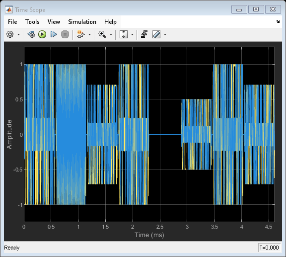
Results
Display the time domain signal and the spectrogram by running the simulation.

More About
In GSM, transmissions consist of TDMA frames. Each GSM TDMA frame consists of eight time slots. The transmission data content of a time slot is called a burst. As described in Section 5.2 of 3GPP TS 45.011, a GSM time slot has a 156.25-symbol duration when using the normal symbol period, which is a time interval of 15/26 ms or about 576.9 microseconds. A guard period of 8.25 symbols or about 30.46 microseconds separates each time slot. The GSM standards describes a symbol as one bit period. Since GSM uses GMSK modulation, there is one bit per bit period. The transmission timing of a burst within a time slot is defined in terms of the bit number (BN). The BN refers to a particular bit period within a time slot. The bit with the lowest BN is transmitted first. BN0 is the first bit period, and BN156 is the last quarter-bit period.
This image from 3GPP TS 45.011 shows the relationship between different frame types and the relationship between different burst types.

This table shows the supported burst types and their characteristics.
| Burst Type | Description | Link Direction | Useful Duration |
|---|---|---|---|
NB | Normal burst | Uplink/Downlink | 147 |
FB | Frequency correction burst | Downlink | 147 |
SB | Synchronization burst | Downlink | 147 |
Dummy | Dummy burst | Downlink | 147 |
AB | Access burst | Uplink | 87 |
Off | No burst sent | Uplink/Downlink | 0 |
Useful duration, described in Section 5.2.2 of 3GPP TS 45.002, is a characteristic of GSM bursts. The useful duration, or useful part, of a burst is defined as beginning halfway through BN0 and ending half a bit period before the start of the guard period. The guard period is the period between bursts in successive time slots. This figure, from Section 2.2 of 3GPP TS 45.004, shows the leading and trailing ½ bit difference between the useful and active parts of the burst.

For more information, see GSM TDMA Frame Parameterization for Waveform Generation.
References
[1] 3GPP TS 45.001. "GSM/EDGE Physical layer on the radio path. General description." 3rd Generation Partnership Project; Technical Specification Group Radio Access Network.
[2] 3GPP TS 45.002. "GSM/EDGE Multiplexing and multiple access on the radio path." 3rd Generation Partnership Project; Technical Specification Group Radio Access Network.
[3] 3GPP TS 45.004. "GSM/EDGE Modulation." 3rd Generation Partnership Project; Technical Specification Group Radio Access Network.