GSM TDMA Frame Parameterization for Waveform Generation
This example shows how to parameterize and generate different GSM TDMA frames and multiframe structures.
Introduction
The GSM standard [1] specifies a TDMA frame as a combination of 8 time slots. Each time slot has a duration of 3/5200 seconds (about 0.577 ms) and a time slot number (TN) from 0 to 7. GSM frames use GMSK modulation, where one symbol is equivalent to one bit. Each time slot is 156.25 bits long. The content of a time slot is called a burst. The transmission timing of a burst within a time slot is defined in terms of the bit number. The bit number (BN) refers to a particular bit period within a time slot. The bit with the lowest bit number is transmitted first. BN0 is the first bit period and BN156 is the last quarter-bit period. This figure shows time frames, time slots, and bursts for a GSM system [1].
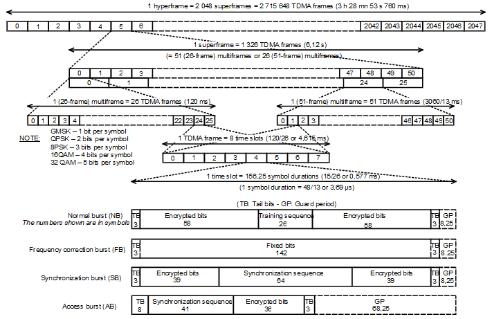
A TDMA contains eight time slots with each timeslot separated by a guard period. Each time slot can carry only one type of burst. Available burst types are: normal burst (NB), frequency correction burst (FB), synchronization burst (SB), access burst (AB), or dummy burst [2]. The different burst types and the guard period are described in these next sections.
Normal Burst (NB)
The normal burst consists of these bit fields and can appear in uplink or downlink frames. All tail bits are zero. Based on the specified training sequence code (TSC), the training sequence field contains one of eight possible training sequences.
normalBurstDescription()
ans=6×3 table
     BitNumber     LengthOfField        ContentsOfField
    ___________    _____________    ________________________

    "0 - 2"         {[     3]}      "tail bits"
    "3 - 60"        {[    58]}      "encrypted bits"
    "61 - 86"       {[    26]}      "training sequence bits"
    "87 - 144"      {[    58]}      "encrypted bits"
    "145 - 147"     {[     3]}      "tail bits"
    "148 - 156"     {[8.2500]}      "guard period (bits)"
Access Burst (AB)
The access burst consists of these bit fields and can appear in uplink frames only. All tail bits are zero.
accessBurstDescription()
ans=5×3 table
    BitNumber     LengthOfField       ContentsOfField
    __________    _____________    ______________________

    "0 - 7"        {[      8]}     "extended tail bits"
    "8 - 48"       {[     41]}     "synch. sequence bits"
    "49 - 84"      {[     36]}     "encrypted bits"
    "85 - 87"      {[      3]}     "tail bits"
    "88 - 156"     {[68.2500]}     "guard period (bits)"
Frequency Correction Burst (FB)
The frequency correction burst consists of these bit fields and can appear in downlink frames only. All tail bits and fixed bits are zero. Modulating all zeros with the GMSK modulator results in a constant phase rotation of -90 degrees for each symbol duration. Therefore, this burst generates an unmodulated carrier with a positive frequency offset of 1625/24 kHz.
frequencyCorrectionBurstDescription()
ans=4×3 table
     BitNumber     LengthOfField       ContentsOfField
    ___________    _____________    _____________________

    "0 - 2"         {[     3]}      "tail bits"
    "3 - 144"       {[   142]}      "fixed bits"
    "145 - 147"     {[     3]}      "tail bits"
    "148 - 156"     {[8.2500]}      "guard period (bits)"
Synchronization Burst (SB)
The synchronization burst consists of these bit fields and can appear in downlink frames only. All tail bits are zero.
synchronizationBurstDescription()
ans=6×3 table
     BitNumber     LengthOfField             ContentsOfField
    ___________    _____________    _________________________________

    "0 - 2"         {[     3]}      "tail bits"
    "3 - 41"        {[    39]}      "encrypted bits"
    "42 - 105"      {[    64]}      "extended training sequence bits"
    "106 - 144"     {[    39]}      "encrypted bits"
    "145 - 147"     {[     3]}      "tail bits"
    "148 - 156"     {[8.2500]}      "guard period (bits)"
Dummy Burst
The dummy burst consists of these bit fields and can appear in downlink frames only. All tail bits are zero. Mixed bits contain a predetermined sequence of ones and zeros.
dummyBurstDescription()
ans=4×3 table
     BitNumber     LengthOfField       ContentsOfField
    ___________    _____________    _____________________

    "0 - 2"         {[     3]}      "tail bits"
    "3 - 144"       {[   142]}      "mixed bits"
    "145 - 147"     {[     3]}      "tail bits"
    "148 - 156"     {[8.2500]}      "guard period (bits)"
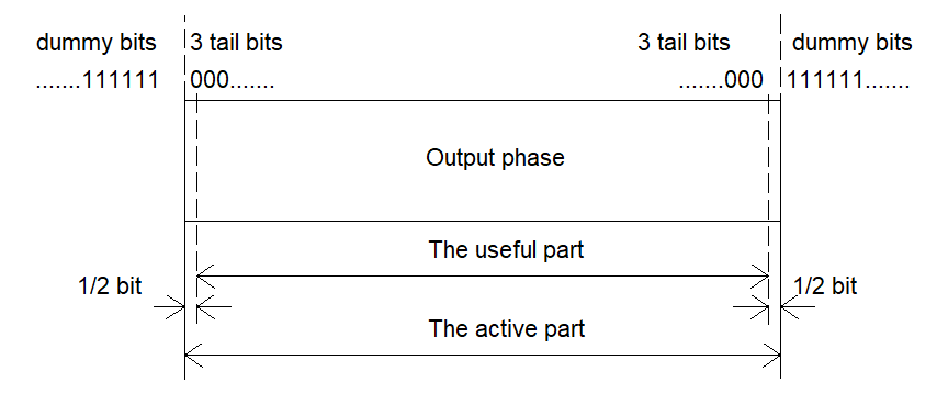
Guard Period
The GSM standard, [3], requires mobile stations to attenuate their transmission during the period between bursts. The ramp-up and ramp-down of the signal power level occurs during the guard periods. The useful part of a burst starts half way through the bit number 0. The useful part ends halfway through BN87 for ABs and BN147 for NBs, FBs, SBs, and dummy bursts. This figure shows the useful and active parts of a burst.
Generate Single Uplink Frame
Configure an uplink GSM TDMA frame using the gsmUplinkConfig object.
cfg = gsmUplinkConfig()
cfg =
  gsmUplinkConfig with properties:

           BurstType: [NB    NB    NB    NB    NB    NB    NB    NB]
    SamplesPerSymbol: 16
                 TSC: [0 1 2 3 4 5 6 7]
         Attenuation: [0 0 0 0 0 0 0 0]
         PulseLength: 4
            RiseTime: 2
           RiseDelay: 0
            FallTime: 2
           FallDelay: 0
Set time slots 2 and 5 to carry access bursts. Since MATLAB® array indices start from 1, but time slots start from 0, set the third and sixth elements of the BurstType to "AB".
cfg.BurstType([2 5] +1) = "AB"cfg =
gsmUplinkConfig with properties:
BurstType: [NB NB AB NB NB AB NB NB]
SamplesPerSymbol: 16
TSC: [0 1 2 3 4 5 6 7]
Attenuation: [0 0 0 0 0 0 0 0]
PulseLength: 4
RiseTime: 2
RiseDelay: 0
FallTime: 2
FallDelay: 0
Assign training sequence codes 3, 5, 1, 7, 0, and 2 to time slots 0, 1, 3, 4, 6, and 7, respectively.
cfg.TSC([0 1 3 4 6 7] +1) = [3 5 1 7 0 2]
cfg =
  gsmUplinkConfig with properties:

           BurstType: [NB    NB    AB    NB    NB    AB    NB    NB]
    SamplesPerSymbol: 16
                 TSC: [3 5 2 1 7 5 0 2]
         Attenuation: [0 0 0 0 0 0 0 0]
         PulseLength: 4
            RiseTime: 2
           RiseDelay: 0
            FallTime: 2
           FallDelay: 0
Generate the baseband samples of the frame using the gsmFrame function.
x = gsmFrame(cfg);
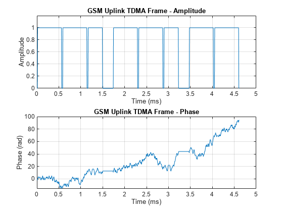
Plot the frame. Get the sample rate of the generated waveform by using the gsmInfo function, and then calculate the time axis values in ms. The plot shows 8 bursts in the frame, with guard periods between each burst. As described in the Access Burst (AB) section, ABs are short burst and have a wider guard period than other bursts.
wfInfo = gsmInfo(cfg);
Rs = wfInfo.SampleRate;
t = (0:length(x) - 1)/Rs*1e3;
subplot(2,1,1)
plot(t,abs(x))
grid on
axis([0 5 0 1.2])
title('GSM Uplink TDMA Frame - Amplitude')
xlabel('Time (ms)')
ylabel('Amplitude')
subplot(2,1,2)
plot(t,unwrap(angle(x)))
grid on
title('GSM Uplink TDMA Frame - Phase')
xlabel('Time (ms)')
ylabel('Phase (rad)')
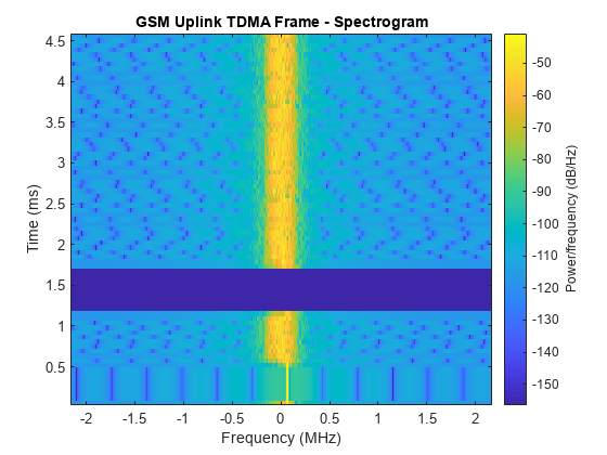
Plot the spectrogram of the frame.
figure
spectrogram(x,500,[],[],Rs,'centered')
title('GSM Uplink TDMA Frame - Spectrogram')

Generate Single Downlink Frame
Configure a downlink GSM TDMA frame using the gsmDownlinkConfig object.
cfg = gsmDownlinkConfig
cfg =
  gsmDownlinkConfig with properties:

           BurstType: [NB    NB    NB    NB    NB    NB    NB    NB]
    SamplesPerSymbol: 16
                 TSC: [0 1 2 3 4 5 6 7]
         Attenuation: [0 0 0 0 0 0 0 0]
         PulseLength: 4
            RiseTime: 2
           RiseDelay: 0
            FallTime: 2
           FallDelay: 0
Set time slots 0 to carry a frequency correction burst, set time slots 4 and 6 to carry dummy bursts, and set time slot 2 to be empty.
cfg.BurstType(0 +1) = "FB";
cfg.BurstType([4 6] +1) = "Dummy";
cfg.BurstType(2 +1) = "Off"
cfg =
  gsmDownlinkConfig with properties:

           BurstType: [FB    NB    Off    NB    Dummy    NB    Dummy    NB]
    SamplesPerSymbol: 16
                 TSC: [0 1 2 3 4 5 6 7]
         Attenuation: [0 0 0 0 0 0 0 0]
         PulseLength: 4
            RiseTime: 2
           RiseDelay: 0
            FallTime: 2
           FallDelay: 0
Generate the baseband samples of the frame using the gsmFrame function. This function inserts random bits instead of encrypted bits.
x = gsmFrame(cfg);
Plot the frame.
wfInfo = gsmInfo(cfg);
Rs = wfInfo.SampleRate;
t = (0:length(x) - 1)/Rs*1e3;
subplot(2,1,1)
plot(t,abs(x))
grid on
axis([0 5 0 1.2])
title('GSM Uplink TDMA Frame - Amplitude')
xlabel('Time (ms)');ylabel('Amplitude')
subplot(2,1,2)
plot(t,unwrap(angle(x)))
grid on
title('GSM Uplink TDMA Frame - Phase')
xlabel('Time (ms)')
ylabel('Phase (rad)')

Plot the spectrogram of the frame. This plot shows the single tone during time slot 0 due to the FB.
figure
spectrogram(x,500,[],[],Rs,'centered')
title('GSM Uplink TDMA Frame - Spectrogram')
Generate Multiframe Structure
Create a 51-frame multiframe structure, as shown in the figure in the Introduction section. Create three gsmDownlinkConfig objects with specified burst configurations. To assemble the 51-frame multiframe, use the first and second gsmDownlinkConfig objects once and repeat the third gsmDownlinkConfig objects for the next 49 frames. Repeat the multiframe structure 3 times.
cfg1 = gsmDownlinkConfig('BurstType',["FB" "NB" "NB" "NB" "NB" "Dummy" "NB" "NB"]);
cfg2 = gsmDownlinkConfig('BurstType',["SB" "NB" "NB" "NB" "NB" "Dummy" "NB" "NB"]);
cfg3 = gsmDownlinkConfig('BurstType',["NB" "NB" "NB" "NB" "NB" "Dummy" "NB" "NB"]);
wfInfo = gsmInfo(cfg);
frameLength = wfInfo.FrameLengthInSamples;
x = zeros(frameLength*51*3,1);
for p=1:3
    x1 = gsmFrame(cfg1);
    x2 = gsmFrame(cfg2);
    x3 = gsmFrame(cfg3,49);
    x((p-1)*frameLength*51+1:p*frameLength*51) = [x1;x2;x3];
end
Simulate Power Control and Propagation Loss Effects
Due to power control and unique propagation loss for each user, the power of each time slot within a frame might be different. Set the power attenuation for time slots 0, 3, and 7 to 2, 6, and 10 dB, respectively.
cfg = gsmUplinkConfig;
cfg.Attenuation([0 3 7] +1) = [2 6 10]
cfg =
  gsmUplinkConfig with properties:

           BurstType: [NB    NB    NB    NB    NB    NB    NB    NB]
    SamplesPerSymbol: 16
                 TSC: [0 1 2 3 4 5 6 7]
         Attenuation: [2 0 0 6 0 0 0 10]
         PulseLength: 4
            RiseTime: 2
           RiseDelay: 0
            FallTime: 2
           FallDelay: 0
x = gsmFrame(cfg);
wfInfo = gsmInfo(cfg);
Rs = wfInfo.SampleRate;
t = (0:length(x) - 1)/Rs*1e3;
plot(t, 20*log10(abs(x)))
axis([0 5 -20 5])
grid on
title('GSM Uplink TDMA Frame Power')
xlabel('Time (ms)')
ylabel('Power (dB)')

Adjust Ramp-Up and Ramp-Down Behavior
GSM bursts must ramp up and ramp down during guard periods [2]. The gsmFrame function implements the rise and fall characteristics of the bursts as a sinusoid. The burst ramps up from zero to full amplitude in the number of symbol durations specified by the RiseTime property value. The resolution of RiseTime is 1/, where represents the SamplesPerSymbol property value of the gsmDownlinkConfig object.
Adjust the ramp-up characteristics of the bursts. Since SamplesPerFrame is 16, you can specify RiseTime with a symbol duration resolution of 0.0625. Set RiseTime to a duration of 3.125 symbols.
cfg = gsmDownlinkConfig;
cfg.RiseTime = 3.125;
Visualize and check if the rise-time characteristics are within the GSM specifications by using the gsmCheckTimeMask function.
gsmCheckTimeMask(cfg)

Move the start of the rise time duration to the left by 1.5 symbols by setting the RiseDelay to -1.5. When RiseDelay is 0, the burst reaches full amplitude at the start of the useful part of the burst.
cfg.RiseDelay = -1.5;
gsmCheckTimeMask(cfg)

The burst ramps down from full amplitude to zero in the number of symbol durations specified by the FallTime property. The resolution of FallTime is 1/, where represents the SamplesPerSymbol property value of the gsmDownlinkConfig object. Set FallTime to a duration of 2.75 symbols.
Move the start of the fall time to the right by 0.25 symbols durations by setting the FallDelay to 0.25. When FallDelay is 0, the burst starts to ramp down from full amplitude at the end of the useful part of the burst.
cfg = gsmDownlinkConfig;
cfg.FallTime = 2.75;
cfg.FallDelay = 0.25;
gsmCheckTimeMask(cfg)

References
[1] 3GPP TS 45.001. "GSM/EDGE Physical layer on the radio path. General description." 3rd Generation Partnership Project; Technical Specification Group Radio Access Network.
[2] 3GPP TS 45.002, "GSM/EDGE Multiplexing and multiple access on the radio path." 3rd Generation Partnership Project; Technical Specification Group Radio Access Network
[3] 3GPP TS 45.004, "GSM/EDGE Modulation." General description." 3rd Generation Partnership Project; Technical Specification Group Radio Access Network
Helper Functions
normalBurstDescription
This function formats a table to show information about normal burst fields.
function d = normalBurstDescription()
BitNumber = ["0 - 2";"3 - 60";"61 - 86";...
    "87 - 144";"145 - 147";"148 - 156"];
LengthOfField = {3;58;26;58;3;8.25};
ContentsOfField = [...
    "tail bits";...
    "encrypted bits";...
    "training sequence bits";...
    "encrypted bits";...
    "tail bits";...
    "guard period (bits)"...
    ];
d = table(BitNumber,LengthOfField,ContentsOfField);
end
frequencyCorrectionBurstDescription
This function formats a table to show information about frequency correction burst fields.
function d = frequencyCorrectionBurstDescription()
BitNumber = ["0 - 2";"3 - 144";"145 - 147";"148 - 156"];
LengthOfField = {3;142;3;8.25};
ContentsOfField = [...
    "tail bits";...
    "fixed bits";...
    "tail bits";...
    "guard period (bits)"...
    ];
d = table(BitNumber,LengthOfField,ContentsOfField);
end
synchronizationBurstDescription
This function formats a table to show information about synchronization burst fields.
function d = synchronizationBurstDescription()
BitNumber = ["0 - 2";"3 - 41";"42 - 105";...
    "106 - 144";"145 - 147";"148 - 156"];
LengthOfField = {3;39;64;39;3;8.25};
ContentsOfField = [...
    "tail bits";...
    "encrypted bits";...
    "extended training sequence bits";...
    "encrypted bits";...
    "tail bits";...
    "guard period (bits)"...
    ];
d = table(BitNumber,LengthOfField,ContentsOfField);
end
dummyBurstDescription
This function formats a table to show information about dummy burst fields.
function d = dummyBurstDescription()
BitNumber = ["0 - 2";"3 - 144";"145 - 147";"148 - 156"];
LengthOfField = {3;142;3;8.25};
ContentsOfField = [...
    "tail bits";...
    "mixed bits";...
    "tail bits";...
    "guard period (bits)"...
    ];
d = table(BitNumber,LengthOfField,ContentsOfField);
end
accessBurstDescription
This function formats a table to show information about access burst fields.
function d = accessBurstDescription()
BitNumber = ["0 - 7";"8 - 48";"49 - 84";...
    "85 - 87";"88 - 156"];
LengthOfField = {8;41;36;3;68.25};
ContentsOfField = [...
    "extended tail bits";...
    "synch. sequence bits";...
    "encrypted bits";...
    "tail bits";...
    "guard period (bits)"...
    ];
d = table(BitNumber,LengthOfField,ContentsOfField);
end