Introduction to Simulink and Simscape | Drilling Systems Modeling & Automation, Part 2
From the series: Drilling Systems Modeling & Automation
Hoisting systems have a bounded and controlled motion of mechanical systems. Modeling plays a role in understanding how the properties and performance of mechanical components and systems affect the overall system design. While the underlying physics are well understood, there exist many different means to model a multibody system, which requires a considerable investment in methods for formulating and solving equations of motion.
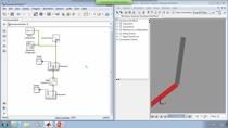
In this video, we demonstrate how easy it is to get started in Simulink and Simscape by using pre-built blocks from the libraries. These libraries span different domains such as mechanical, electrical and hydraulic. We start off by using templates to build the drawworks drum and mass assembly. Then we add joints, connections to complete the mechanical model. We can also import assemblies from CAD software such as SOLIDWORKS. This saves substantial time for kinematics assemblies.
For the electrical control systems of the rig, we draw from pre-built blocks for the electrical domain such as 3-phase rectifier, filter/chopper, field controller and induction motor. The system is complete after the addition of a simple PID loop. MathWorks offers the complete reference application on our File Exchange at no cost for usage.
Published: 2 Jul 2020
Welcome back. My name is Jonathan LeSage and I'm an application engineer with MathWorks. Last time we looked at how we could build an integrated simulation of both hardware and software in Simulink to do testing and optimization. Today, we're going to take a step back and see how we can build those up from scratch.
Now if you're just joining us, this is the system that we're working with. It's a hoisting machine called the draw works, very common in the oil and gas industry. It's also safety critical system, the top drive essentially this load is going to be carrying the drill string up and down. It's going to be raising and lowering this hundreds of times. And we're dealing with very high loads and heavy weights and, you know, systems that have operational bounds.
And so if we operate this outside of those bounds, we can have disastrous effects. This thing can hit the top or crown out or hit the bottom. Now when we're talking about building digital twins or models of systems, there's many different ways you can do that. You can go from first principles, basically building a model up from dynamic equations or in our tools we have blocks that represent different components like drives or springs. Or you can import things from CAD as well.
To the other side, which is basically a purely black box model, purely data driven. These are models that basically can use data to learn. So typically things like machine learning, deep learning, these are where these topics come up. The beauty is you can actually combine these techniques together in Simulink and come up with kind of gray box models. Some parts are based off of first principle. Some parts are based off of data driven models. And you can also do model calibration using data to tune those models.
Now, we're going to be using a library in Simulink called Simscape. It's a block diagram-based modeling environment. We have components for different domains. And we're going to be focused primarily on the mechanical domain today. All right. So let's take a look at the tools.
So I'm hopping back over to MATLAB. Now MATLAB is kind of our platform tool, great for data analytics for working and automating things. But we're going to be working in our tool Simulink. Simulink is a block diagram model, as I mentioned. So if we go ahead and launch this up, a lot of times people start with blank models. And that's great, you know, if you have built Simulink models before. You can jump in and start building these models.
However, if you know you're going to be building a physical model, so maybe you're working with an electrical simulation or a mechanical simulation. I actually recommend scrolling down and using these Simscape templates. For today, I'm going to be working primarily in the multi-body domain, which is a really rigid body dynamics tool which we can import models from CAD for. So I'll just use this template to start. OK.
Now Simulink, as you can see, is a block diagram based modeling environment. When you use these templates, you get a lot of the common blocks in your model all ready to start. So you can just jump in and start building things up. So just to quickly review when you're building a model for 3D rigid body dynamics, we have to have a world reference frame. This is kind of like the ground. Where do we measure zero from. We have a block here that's basically lets us dictate which direction gravity is in. Either, you know, negative y or negative z. And then we have a solver configuration that lets us add components.
Now, what I'm going to actually build for this is a very simple kind of mechanism that allows me to basically raise and lower a block up and down, similar to our draw works. So what we need is basically a drum which can rotate, and then a mass which it can hoist. OK? And the whole idea of the multi-body environment is we have these components that represent the degrees of freedom, the joints, the connections. And then the rigid bodies themselves. There is the capability to do some flexibility as well.
So what I'm going to do is I'm going to grab a revolute joint. That's going to represent the ability of our drum to spin, connect that up. And one thing to keep in mind is these revenue joints, the pivot point is around the z direction and the base axis here is the y. So I'm just going to do a quick little pivot. Go ahead and pivot this around the minus y by 90. OK.
This will get this aligned correctly. And now I want this to actually maybe have a mass so I can come over here and grab a cylindrical body. And you can rotate this around, that's control R, connect that up. I'll make this cylindrical solid, maybe I'll have a more realistic radius, 0.1.
And then I can actually start to connect up the belts and ropes. And so we have a little sub-library here. I can grab the belt and cable spool. Connect that up. And then, maybe have a free end. So rather than have any employees in this case, we're just going to have this connect directly to the mass, connect up the rope.
And the last thing here is we're going to add this belt and cables property block. This allows us to kind of customize what this cable looks like. And lastly, we'll connect up a solid for this to talk to.
Now this might seem like this is complete. We got kind of the bare bones here. If I hit run, we're going to see that this model's not quite ready. And really, the whole problem here-- we'll see that we get a diagnostic viewer error-- is that this model is not assembled singularity violation.
So this is an error that sometimes you see. And what this represents is essentially two bodies are directly on top of each other. So my cylindrical solid here, you can see, and my brick, my simple models here are right on top of each other. And we have a violation.
And so what we can do to kind of alleviate this is I'm going to actually add another joint here, prismatic. You can click and search as well. And I'm going to go ahead and specify that I want this block to start away from zero. So maybe I'll say a minus 1 meter. And so now if I push play, we should actually see something interesting. So we see the block and that block falls.
Now this is our drum. This is the rope. And you see that that just falls directly. Now the reason that that's falling and almost like never stopping is currently this joint is unactuated. And so what we can start to do with that actuation to this joint and maybe start to control.
So what I'm going to do, just real quick, is actually do a couple more things to make this a little more interesting. Rather than having a brick, we'll go ahead and grab a CAD model. So I'll grab a body element. I'll grab a file solid here. This lets me actually represent anything. So I'll just go into my CAD files here, grab my top drive. We'll see that here's my top drive model. I'll do a couple of other things. I'll give it some inertia.
In this case, I'll just say it weighs 100 kilograms. And then lastly, what I'm going to do, this default frame is our center of mass. So you see it's right there. What I'd rather do instead of that is go ahead and put a frame right at the tip where I would actually be interfacing with this. So I can select that surface. I can say use this geometric feature.
And in this particular case, we want to make sure that the z-axis is up. So I just pivoted that. And we're good to go. So I can say, OK. OK. And now I actually will have a file solid. If I push play again. Let me go ahead and restart this. You'll see that I have a Drawworks top drive going up and down. So I actually have a shape from CAD.
And now what I'll do is I'll actually start to add the actuation. So in this joint, my revolute joint. I'll go into activation. You'll notice the default is no torque. But I can change this over to provide by input. We'll get that torque port there. Maybe I want to actually measure something. So I'll sense velocity.
So I'm actually going to be measuring the velocity of this going up and down. And we can do some simple feedback. So I will connect this guy up. Connect this guy up. These are basically signals that will tell me what units these are in. And I'll just do a really simple feedback controllers. So I'll just grab something like a PID. And again, you can just grab these out of the Simulink library directly, grab a sum. We'll make that a difference. So I'm just going to do a simple feedback loop.
That will go in there. Then we'll do like a step input. And maybe we'll make this step 5 seconds. And we'll go down at 5 meters per second. And then we'll go up at 5 meters per second. And I know that this p and I are probably too low. I'm going to just manually jump these up a little bit. But I could actually jump in and start using our tuning tools directly already. And that would linearize our model and get us going real quick. But let's take a look. So now I can take a look at the scope.
And we'll see, OK, minus 5 and plus 5. And now if we maybe re-watch our video here, zoom this out a little bit. I'll fit it to the view. You can see it go down and then back up. OK? So that's a quick introduction to how you can build a model from scratch.
Now, the thing to note is we can actually import all this stuff directly from CAD. So if you have a solidworks assembly or other tools, you can actually import these and autobuild stuff directly. And it will save you a lot of time, especially for kinematic assemblies. All right. We'll see you in the next video.


