Main Content

wlanHTDataRecover

Recover bits from HT-Data field

Description

dataBits = wlanHTDataRecover(rxDataSig,chEst,noiseVarEst,cfgHT) recovers dataBits, a column vector of bits, from rxDataSig, the received HT-Data field of a high-throughput-mixed (HT-mixed) transmission. The function recovers dataBits by using chEst, a channel estimate for the occupied subcarriers, noiseVarEst, an estimate of noise variance, and cfgHT, a configuration object that contains HT transmission parameters.

For more information about the HT-Data field, see HT-Data Field. For more information about the HT-mixed format, see HT-Mixed Format.

example

dataBits = wlanHTDataRecover(rxDataSig,chEst,noiseVarEst,cfgHT,Name,Value) specifies algorithm options by using one or more name-value pair arguments. For example, 'LDPCDecodingMethod','layered-bp' specifies the layered belief propagation low-density parity-check (LDPC) decoding algorithm.

[dataBits,eqSym] = wlanHTDataRecover(___) returns eqSym, the equalized OFDM symbols that comprise the data subcarriers of the HT-Data field, using any input argument combination from the previous syntaxes.

[dataBits,eqSym,cpe] = wlanHTDataRecover(___) returns cpe, the common phase error between the received and expected OFDM symbols.

example

[dataBits,eqSym,cpe,ae] = wlanHTDataRecover(___) returns ae, the average amplitude error with respect to the estimated received pilots.

example

Examples

collapse all

Recover bits from the HT-Data field of an HT-mixed waveform transmitted through an additive white Gaussian noise (AWGN) channel.

Configure an HT-mixed transmission and generate the corresponding HT-Data field.

cfgHT = wlanHTConfig('PSDULength',1024);
psduLength = 8*cfgHT.PSDULength;
bits = randi([0 1],psduLength,1);
txDataSig = wlanHTData(bits,cfgHT);

Transmit the signal through an AWGN channel with a signal-to-noise ratio (SNR) of 10 dB.

snr = 10;
noiseVarEst = 10^(-snr/10);
rxDataSig = awgn(txDataSig,snr);

Specify a channel estimate. Because the signal does not pass through a fading channel, a vector of ones is a perfect estimate. For a channel bandwidth of 20 MHz, the HT-SIG field contains 52 data subcarriers and 4 pilot subcarriers.

chEst = ones(56,1);

Recover the bits from the received HT-Data field and confirm that the recovered bits match the transmitted bits.

dataBits = wlanHTDataRecover(rxDataSig,chEst,noiseVarEst,cfgHT);
isequal(dataBits,bits)
ans = logical
   1

Configure an HT-mixed transmission with a channel bandwidth of 40 MHz and a PSDU length of 1024 bytes, then generate the corresponding HT-Data field.

psduLength = 1024;
cfgHT = wlanHTConfig('ChannelBandwidth','CBW40','PSDULength',psduLength);
bits = randi([0 1],8*psduLength,1);
txDataSig = wlanHTData(bits,cfgHT);

Pass the signal through an AWGN channel with an SNR of 7 dB.

snr = 7;
noiseVarEst = 10^(-snr/10);
rxDataSig = awgn(txDataSig,7);

Specify a channel estimate.

chEst = ones(114,1);

Recover the bits from the received HT-Data field and confirm that the recovered bits match the transmitted bits.

[dataBits,eqSym,cpe] = wlanHTDataRecover(rxDataSig,chEst,noiseVarEst, ...
    cfgHT,'EqualizationMethod','ZF');
isequal(bits,dataBits)
ans = logical
   1

Calculate and display the maximum common phase error.

max(abs(cpe))
ans = 
0.3928

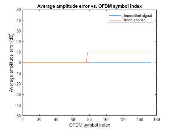
Investigate how applying an amplitude droop affects the amplitude error of the HT-Data field generated from an HT-mixed signal.

Configure an HT-mixed transmission with a channel bandwidth of 40 MHz and a PSDU length of 1024 bytes, then generate the corresponding HT-Data field.

psduLength = 1024;
cfgHT = wlanHTConfig('ChannelBandwidth','CBW40','PSDULength',psduLength);
bits = randi([0 1],8*psduLength,1);
tx = wlanHTData(bits,cfgHT);

Modify the signal by applying an amplitude droop of 10 dB, starting at the halfway point.

signalLength = size(tx,1);
droopGain = 10;
droopGainLinear = 10^(droopGain/20);
txDroop = [ones(signalLength/2,1); droopGainLinear*ones(signalLength/2,1)].*tx;

Specify a channel estimate.

chEst = ones(114,1);

Recover the bits from the ideal and impaired HT-Data fields and confirm that the recovered bits match the transmitted bits.

[databits_1,eqSym_1,cpe_1,ae_1] = wlanHTDataRecover(tx,chEst,0, ...
    cfgHT,EqualizationMethod="ZF",PilotAmplitudeTracking="PreEQ");
[databits_2,eqSym_2,cpe_2,ae_2] = wlanHTDataRecover(txDroop,chEst,0, ...
    cfgHT,EqualizationMethod="ZF",PilotAmplitudeTracking="PreEQ");
isequal(databits_1,databits_2,bits)
ans = logical
   1

Plot the absolute value of the measured amplitude errors for the ideal and impaired HT-Data fields.

plot(abs(ae_1))
title('Average amplitude error vs. OFDM symbol index')
ylabel('Average amplitude error (dB)')
xlabel('OFDM symbol index')
ylim([-50 50])
hold on
plot(abs(ae_2))
legend('Unmodified signal', 'Droop applied')

Figure contains an axes object. The axes object with title Average amplitude error vs. OFDM symbol index, xlabel OFDM symbol index, ylabel Average amplitude error (dB) contains 2 objects of type line. These objects represent Unmodified signal, Droop applied.

Input Arguments

collapse all

Received HT-Data field, specified as a complex-valued array of size NS-by-NR.

  • NS is the number of time-domain samples.

  • NR is the number of receive antennas.

Data Types: double | single
Complex Number Support: Yes

Channel estimate, specified as a complex-valued array of size NST-by-NSTS-by-NR.

  • NST is the number of occupied subcarriers.

  • NSTS is the number of space-time streams.

  • NR is the number of receive antennas.

Data Types: double | single
Complex Number Support: Yes

Noise variance estimate, specified as a nonnegative scalar.

Data Types: double | single

HT transmission parameters, specified as a wlanHTConfig object.

Name-Value Arguments

Specify optional pairs of arguments as Name1=Value1,...,NameN=ValueN, where Name is the argument name and Value is the corresponding value. Name-value arguments must appear after other arguments, but the order of the pairs does not matter.

Before R2021a, use commas to separate each name and value, and enclose Name in quotes.

Example: 'PilotPhaseTracking','None' disables pilot phase tracking.

OFDM symbol sampling offset represented as a fraction of the cyclic prefix (CP) length, specified as the name-value pair consisting of 'OFDMSymbolOffset' and a scalar in the interval [0, 1]. The value you specify indicates the start location for OFDM demodulation relative to the beginning of the CP. The value 0 represents the start of the CP, and the value 1 represents the end of the CP.

Different values of the OFDMSymbolOffset argument

Data Types: double

Equalization method, specified as one of these values.

  • 'MMSE' — The receiver uses a minimum mean-square error equalizer.

  • 'ZF' — The receiver uses a zero-forcing equalizer.

When the received signal has multiple receive antennas, the function exploits receiver diversity during equalization. When the number of transmitted space-time streams is one and you specify this argument as 'ZF', the function performs maximal-ratio combining.

Data Types: char | string

Pilot phase tracking, specified as the name-value pair consisting of 'PilotPhaseTracking' and one of these values.

  • 'PreEQ' — Enable pilot phase tracking, which the function performs before any equalization operation.

  • 'None' — Disable pilot phase tracking.

Data Types: char | string

Pilot amplitude tracking, specified as the comma-separated pair consisting of 'PilotAmplitudeTracking' and one of these values.

  • 'None' — Disable pilot amplitude tracking.

  • 'PreEQ' — Enable pilot amplitude tracking, which the function performs before any equalization operation.

Note

Due to the limitations of the algorithm used, disable pilot amplitude tracking when filtering a waveform through a MIMO fading channel.

Data Types: char | string

LDPC decoding algorithm, specified as the comma-separated pair consisting of 'LDPCDecodingMethod' and one of these values.

  • 'bp' — Use the belief propagation (BP) decoding algorithm. For more information, see Belief Propagation Decoding.

  • 'layered-bp' — Use the layered BP decoding algorithm, suitable for quasi-cyclic parity check matrices (PCMs). For more information, see Layered Belief Propagation Decoding.

  • 'norm-min-sum' — Use the layered BP decoding algorithm with the normalized min-sum approximation. for more information, see Normalized Min-Sum Decoding.

  • 'offset-min-sum' — Use the layered BP decoding algorithm with the offset min-sum approximation. For more information, see Offset Min-Sum Decoding.

Note

When you specify this input as 'norm-min-sum' or 'offset-min-sum', the function sets input log-likelihood ratio (LLR) values that are greater than 1e10 or less than -1e10 to 1e10 and -1e10, respectively. The function then uses these values when executing the LDPC decoding algorithm.

Dependencies

To enable this argument, set the ChannelCoding property of the cfgHT input to 'LDPC'.

Data Types: char | string

Scaling factor for normalized min-sum LDPC decoding, specified as the name-value argument consisting of MinSumScalingFactor and a scalar in the interval (0, 1].

Dependencies

To enable this argument, specify the 'LDPCDecodingMethod' name-value argument as "norm-min-sum".

Data Types: double

Offset for offset min-sum LDPC decoding, specified as the name-value argument consisting of MinSumOffset and a nonnegative scalar.

Dependencies

To enable this argument, specify the 'LDPCDecodingMethod' name-value argument as offset-min-sum.

Data Types: double

Maximum number of LDPC decoding iterations, specified as the comma-separated pair consisting of 'MaximumLDPCIterationCount' and a positive integer.

Dependencies

To enable this argument, set the ChannelCoding property of the cfgHT input to 'LDPC'.

Data Types: double

Enable early termination of LDPC decoding, specified as the comma-separated pair consisting of 'EarlyTermination' and 1 (true) or 0 (false).

  • When you set this value to 0 (false), LDPC decoding completes the number of iterations specified in the 'MaximumLDPCIterationCount' name-value pair argument regardless of parity check status.

  • When you set this value to 1 (true), LDPC decoding terminates when all parity checks are satisfied.

Dependencies

To enable this argument, set the ChannelCoding property of the cfgHT input to 'LDPC'.

Data Types: logical

Output Arguments

collapse all

Bits recovered from HT-Data field, returned as a binary-valued column vector of length 8×LPSDU, where LPSDU is the length of the PSDU in bytes.

Data Types: int8

Equalized OFDM symbols comprising the HT-Data field, returned as a complex-valued array of size NSD-by-NSym-by-NSS.

  • NSD is the number of data subcarriers.

  • NSym is the number of OFDM symbols in the HT-Data field.

  • NSS is the number of spatial streams.

Data Types: double | single
Complex Number Support: Yes

Common phase error between the received and expected OFDM symbols, in radians, returned as a real-valued column vector. The length of this output is NSym, the number of OFDM symbols in the HT-Data field. This output is averaged over the receive antennas.

Data Types: double | single

Average amplitude error, in dB, returned as a real-valued array of size NSym-by- NR.

  • NSym is the number of OFDM symbols in the HT-Data field.

  • NR is the number of receive antennas.

Each element of this matrix contains the amplitude error for all subcarriers with respect to the estimated received pilots for the corresponding OFDM symbol and receive antenna.

Data Types: double | single

More About

collapse all

HT-Data Field

The HT-Data field follows the last HT-long training field (HT-LTF) of an HT-mixed packet.

The HT-Data field in an HT-mixed packet

The HT-Data field carries one or more frames from the medium access control (MAC) layer and consists of four subfields.

  • Service — Contains 16 zeros to initialize the data scrambler

  • PSDU — Variable-length field containing a PLCP service data unit (PSDU)

  • Tail — Contains six zeros for each encoding stream, required to terminate a convolutional code

  • Pad Bits — Variable-length field required to ensure that the HT-Data field consists of an integer number of symbols

HT-Mixed Format

HT-mixed transmissions contain a PLCP header such that devices operating in the HT and non-HT modes can decode them.

Algorithms

collapse all

This function supports these four LDPC decoding algorithms.

Belief Propagation Decoding

The function implements the BP algorithm based on the decoding algorithm presented in [2]. For transmitted LDPC-encoded codeword c=(c0,c1,,cn1), the input to the LDPC decoder is the LLR given by

L(ci)=log(Pr(ci=0|channel output for ci)Pr(ci=0|channel output for ci)).

In each iteration, the function updates the key components of the algorithm based on these equations:

L(rji)=2atanh(iVj\{i}tanh(12L(qij))),

L(qij)=L(ci)+j'Ci\{j}L(rji), initialized as L(qij)=L(ci) before the first iteration, and

L(Qi)=L(ci)+jCiL(rji).

At the end of each iteration, L(Qi) is an updated estimate of the LLR value for the transmitted bit, ci. The value L(Qi) is the soft-decision output for ci. If L(Qi) is negative, the hard-decision output for ci is 1. Otherwise, the output is 0.

Index sets Ci\{j} and Vj\{i} are based on the PCM such that the sets Ci and Vj correspond to all nonzero elements in column i and row j of the PCM, respectively.

This figure demonstrates how to compute these index sets for PCM H for the case i = 5 and j = 3.

Compute index sets for PCM

To avoid infinite numbers in the algorithm equations, atanh(1) and atanh(–1) are set to 19.07 and –19.07, respectively. Due to finite precision, MATLAB® returns 1 for tanh(19.07) and –1 for tanh(–19.07).

When you specify the 'EarlyTermination' name-value pair argument as 0 (false), the decoding terminates after the number of iterations specified by the 'MaximumLDPCIterationCount' name-value pair argument. When you specify the 'EarlyTermination' name-value pair argument as 1 (true), the decoding terminates when all parity checks are satisfied (HcT=0) or after the number of iterations specified by the 'MaximumLDPCIterationCount' name-value pair argument.

Layered Belief Propagation Decoding

The function implements the layered BP algorithm based on the decoding algorithm presented in Section II.A of [3]. The decoding loop iterates over subsets of rows (layers) of the PCM.

For each row, m, in a layer and each bit index, j, the implementation updates the key components of the algorithm based on these equations.

(1) L(qmj)=L(qj)Rmj

(2) Ψ(x)=log(|tanh(x/2)|)

(3) Amj=nN(m)\{j}Ψ(L(qmn))

(4) smj=nN(m)\{j}sgn(L(qmn))

(5) Rmj=smjΨ(Amj)

(6) L(qj)=L(qmj)+Rmj

For each layer, the decoding equation (6) works on the combined input obtained from the current LLR inputs, L(qmj), and the previous layer updates, Rmj.

Because the layered BP algorithm updates only a subset of the nodes in a layer, this algorithm is faster than the BP algorithm. To achieve the same error rate as attained with BP decoding, use half the number of decoding iterations when using the layered BP algorithm.

Normalized Min-Sum Decoding

The function implements the normalized min-sum decoding algorithm by following the layered BP algorithm with equation (3) replaced by

Amj=minnN(m)\{j}(α|L(qmn)|),

where α is the scaling factor specified by the 'MinSumScalingFactor' name-value pair argument. This equation is an adaptation of equation (4) presented in [4].

Offset Min-Sum Decoding

The function implements the offset min-sum decoding algorithm by following the layered BP algorithm with equation (3) replaced by

Amj=max(minnN(m)\{j}(|L(qmn)|β), 0),

where β is the offset specified by the 'MinSumOffset' name-value pair argument. This equation is an adaptation of equation (5) presented in [4].

References

[1] IEEE Std 802.11™-2020 (Revision of IEEE Std 802.11-2016). “Part 11: Wireless LAN Medium Access Control (MAC) and Physical Layer (PHY) Specifications.” IEEE Standard for Information Technology — Telecommunications and Information Exchange between Systems — Local and Metropolitan Area Networks — Specific Requirements.

[2] Gallager, Robert G. Low-Density Parity-Check Codes. Cambridge, MA: MIT Press, 1963.

[3] Hocevar, D.E. "A Reduced Complexity Decoder Architecture via Layered Decoding of LDPC Codes." In IEEE Workshop on Signal Processing Systems, 2004. SIPS 2004., 107-12. Austin, Texas, USA: IEEE, 2004. https://doi.org/10.1109/SIPS.2004.1363033.

[4] Jinghu Chen, R.M. Tanner, C. Jones, and Yan Li. "Improved Min-Sum Decoding Algorithms for Irregular LDPC Codes." In Proceedings. International Symposium on Information Theory, 2005. ISIT 2005., 449-53, 2005. https://doi.org/10.1109/ISIT.2005.1523374.

Extended Capabilities

C/C++ Code Generation
Generate C and C++ code using MATLAB® Coder™.

Version History

Introduced in R2015b

expand all