Configure Hardware Interfaces
NI™ USRP™ radios are software-defined radios (SDRs) that consist of a configurable radio front end and an FPGA that can perform digital functions. The diagram shows a conceptual overview of the interfaces between the internal subsystems in an NI USRP radio, and between the radio and the host.

When you design your user logic, referred to as the design under test (DUT), you can include register interfaces and the following data streaming interfaces:
DUT input data streaming interfaces
From the radio front end to receive data from the air
From the host
From the host through the PL DDR buffer
DUT output data streaming interfaces:
To the radio front end to transmit data over the air
To the host
To the host through the PL DDR buffer
Model your data streaming interfaces using the simplified AXI-stream protocol. For details, see Simplified AXI-Stream Protocol.
To map your DUT data streaming interfaces, see Map Target Interfaces in step 4 of the workflow.
Simplified AXI-Stream Protocol
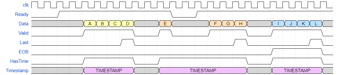
Model the streaming interfaces in your model using the simplified AXI-Stream protocol. Include the following signals for each streaming data interface:
Data
Valid
Ready
Last
Optionally, you can also include these signals:
EOB
Timestamp and HasTime
The timing diagram shows an example of these signals with a data packet length of 4 samples and a burst length of 3 packets.
Data Signal
The data signal is a 32-bit bus that carries data between subsystems.
For streaming connections to the radio, the data signal is a 32-bit unsigned integer, where bits <31:16> contain the quadrature component of the IQ data and bits <15:0> contain the in-phase component. Data is sent and received in a 256 sample packet. Packets are sent in a burst, which is an arbitrary number of consecutive data packets. You send or receive the number of bursts required to contain the requested number of samples.
Valid Signal
The valid signal is a flag that is asserted when the data signal has valid data. This signal is held until a ready signal is received.
Ready Signal
The ready signal is a flag that is asserted when data is ready to be received. When the ready signal is deasserted, data is held until it is reasserted. This can be used to apply back pressure.
Last Signal
The last signal is a flag that is asserted for the duration of the last sample in a data packet. This signal indicates the end of a packet of data.
End of Burst (EOB) Signal
The EOB signal is an optional signal that is asserted for the duration of the last data packet in a burst of data packets.
Timestamp Signal
the timestamp signal is an optional 64-bit signal that contains the time of the first data sample in the packet. The time is the number of master clock cycles since the radio was set up. The master clock depends on the sample rate. For details, see Baseband Sample Rate in NI USRP Radios.
HasTime Signal. The HasTime signal is asserted when a valid timestamp signal is present.
Related Topics
You can also select a web site from the following list:
Americas
- América Latina (Español)
- Canada (English)
- United States (English)
Europe
- Belgium (English)
- Denmark (English)
- Deutschland (Deutsch)
- España (Español)
- Finland (English)
- France (Français)
- Ireland (English)
- Italia (Italiano)
- Luxembourg (English)
- Netherlands (English)
- Norway (English)
- Österreich (Deutsch)
- Portugal (English)
- Sweden (English)
- Switzerland
- United Kingdom (English)