Symbol Modulator
Libraries:
Wireless HDL Toolbox /
Modulation
Description
The Symbol Modulator block modulates data bits to complex data symbols. The block accepts data bits, along with a control signal, and outputs a modulated complex symbol with a valid signal. Each complex symbol comprises a standard number of bits based on the modulation type, as shown in this table. The modulation order specifies the number of points in the signal constellation.
| Modulation Type | Number of Bits Per Symbol (NBPS) | Modulation Order |
|---|---|---|
| BPSK | 1 | 2 |
| QPSK | 2 | 4 |
| 8-PSK | 3 | 8 |
| 16-PSK | 4 | 16 |
| 16-QAM | 4 | 16 |
| 32-PSK | 5 | 32 |
| 64-QAM | 6 | 64 |
| 256-QAM | 8 | 256 |
| 1024-QAM | 10 | 1024 |
| 4096-QAM | 12 | 4096 |
The block supports both scalar and vector inputs when you set the Modulation
source parameter to Property. It supports only scalar
input when you set the Modulation source parameter to Input
port. You can use this block to develop transmitters in a digital
communication system. The block provides an architecture suitable for HDL code generation and
hardware deployment.
Examples
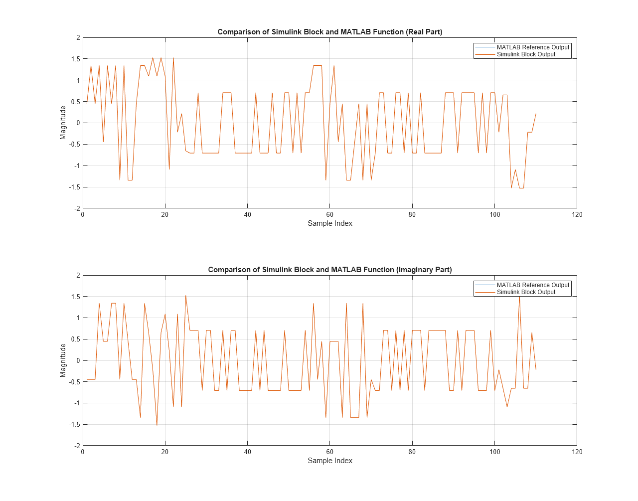
Symbol Modulation of Data Bits
Modulate data bits to complex data symbols.
Ports
Input
Output
Parameters
Algorithms
The latency of the block varies with the type of input: scalar or vector and the
modulation source: Property or Input
port.
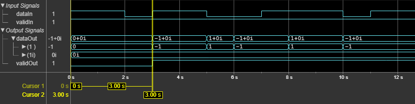
This figure shows a sample output and latency of the Symbol Modulator
block when you specify a scalar input, set the Modulation source
parameter to Property, set the Modulation
parameter to BPSK, and use the default settings for the other
block parameters.
The latency of the block is equal to NBPS + 2 clock cycles. This calculation shows that the latency of the block is 3 clock cycles, as shown in this figure.
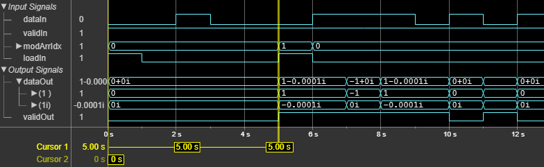
This figure shows a sample output and latency of the Symbol Modulator
block when you specify a scalar input, set the Modulation source
parameter to Input port, set the Modulation
array to {"BPSK","QPSK"}, and use the default settings for
the other block parameters. The latency of the block is equal to NBPS +
4 clock cycles. The NBPS value corresponds to the modulation array
index specified through the modArrIdx port. This calculation shows
that the latency of the block is 5 clock cycles, as shown in this figure.
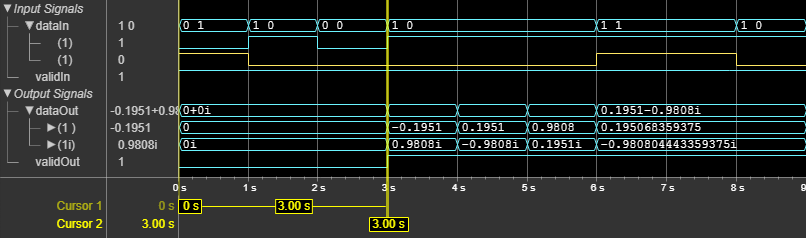
This figure shows a sample output and latency of the Symbol Modulator
block when you specify a vector input, set the Modulation source
parameter to Property, set the Modulation
parameter to QPSK, and use the default settings for the other
block parameters. The latency of the block is 3 clock cycles, as shown in this
figure.
Extended Capabilities
Version History
Introduced in R2025a