Symbol Modulation of Data Bits
This example shows how to modulate data bits to complex data symbols using the Symbol Modulator block. Generate a set of random inputs and provide them as an input to the block and the MATLAB® function refSymMod. Compare the output of the block with the output of the refSymMod function. This reference function uses pskmodqammod
This example showcases the block configuration, where the Modulation source parameter is set to Input port, the Constellation ordering type and Phase offset type parameters are set to User-defined, and the Normalization method is set to Average power.
Set Up Input Variables
Set up input variables. You can change the variable values in this section based on your requirements. Specify the modArrIdx, constellMapArray, phaseOffArray with respective to the modulation types specified in the modulationArray. In this example modulationArray is specified as {"64-QAM","QPSK","16-QAM"}.
The modArrIdx values must be scalar in the range [0 2], where 0, 1, and 2 correspond to "64-QAM", "QPSK", and "16-QAM", respectively. The constellMapArray must be a row vector cell array that contains constellations corresponding to "64-QAM", "QPSK", and "16-QAM", respectively. The phaseOffsetArray must be a row vector cell array that contains phase offsets corresponding to "64-QAM", "QPSK", and "16-QAM", respectively.
rng(0);
numBits = 60;
modulationArray = {"64-QAM","QPSK","16-QAM"};
modArrIdx = [2; 0; 1; 2; 1; 0];
constellOrderType =  'User-defined'; % 'Default' 'User-defined'
constell1 = [4 5 7 6 2 3 1 0 12 13 15 14 10 11 9 8 28 29 31 30 26 ...
             27 25 24 20 21 23 22 18 19 17 16 52 53 55 54 50 51 49 ...
             48 60 61 63 62 58 59 57 56 44 45 47 46 42 43 41 40 36 ...
             37 39 38 34 35 33 32];
constell2 = [3 1 0 2];
constell3 = [2 3 1 0 6 7 5 4 14 15 13 12 10 11 9 8];
constellMapArray = {constell1,constell2,constell3};
phaseOffsetType = 'User-defined';%  'Default' 'User-defined'
phaseOffArray = [0 pi/4 0];
normMethod = 'Average power';    % 'Average power' 'Minimum distance between symbols'
avgPower = 2;
minDis = 1/8;
modSource = 'Input port';
outputDataType = 'Custom';       % Output data type can be 'double', 'single', or 'Custom'
wordLength = 16;                 % Output word length can be in the range [3, 32]

numframes = length(modArrIdx);
dataSymbols  = cell(1,numframes);
modArrIdxTmp = cell(1,numframes);
loadTmp = cell(1,numframes);
referenceOutput = cell(1,numframes);
modOrder = cell(1,numframes);
Generate Frames of Random Samples
Generate bits using the randi function.
for ii = 1:numframes
    dataSymbols{ii} = randi([0 1],numBits,1);
    modArrIdxTmp{ii} = fi(modArrIdx(ii)*ones(numBits,1),0,4,0);
    loadTmp{ii} = boolean([1;zeros(numBits-1,1)]);
end
Convert Frames to Stream of Random Samples
Convert frames of complex random samples to a stream of complex random samples that the block can accept as input.
idlecyclesbetweensamples = 0;
idlecyclesbetweenframes = 0;
[dataIn,ctrl] = whdlFramesToSamples(dataSymbols,idlecyclesbetweensamples, ...
    idlecyclesbetweenframes);
[modArrIdxIn,~] = whdlFramesToSamples(modArrIdxTmp,idlecyclesbetweensamples, ...
    idlecyclesbetweenframes);
[loadIn,~] = whdlFramesToSamples(loadTmp,idlecyclesbetweensamples, ...
    idlecyclesbetweenframes);
validIn = logical(ctrl(:,3)');

sampletime = 1;
samplesizeIn = 1;
simTime = size(ctrl,1)*2;
Run Simulink Model
The symbolMod subsystem contains the Symbol Modulator block. Running the model imports the input signal variables dataIn, validIn, modArrIdxIn, and loadIn to the block from the script. The model exports a stream of modulated output samples dataOut and validOut signals from the block to the MATLAB workspace.
modelname = 'symbolModulator';
open_system(modelname);
set_param([modelname '/SymbolMod/Symbol Modulator'],'ModulationSource',modSource)
set_param([modelname '/SymbolMod/Symbol Modulator'],'ConstOrder',constellOrderType)
set_param([modelname '/SymbolMod/Symbol Modulator'],'PhaseOffsetType',phaseOffsetType)
set_param([modelname '/SymbolMod/Symbol Modulator'],'NormMethod',normMethod)
set_param([modelname '/SymbolMod/Symbol Modulator'],'OutputDataType',outputDataType)
symModOut = sim(modelname);
modOut =  symModOut.dataOut.Data(symModOut.validOut.Data);

Modulate Stream Samples Using MATLAB Function
To symbol modulate the stream of random bits, provide them as input to the refSymMod function. You can use the output of this function as a reference to compare the output of the block.
for ii = 1:numframes
 inpParamFr.modulationArray = modulationArray{modArrIdx(ii)+1};
 inpParamFr.modArrIdx = modArrIdx(ii);
 inpParamFr.constellOrderType = constellOrderType;
 inpParamFr.constellMapArray = constellMapArray{modArrIdx(ii)+1};
 inpParamFr.phaseOffsetType = phaseOffsetType;
 inpParamFr.phaseOffArray = phaseOffArray(modArrIdx(ii)+1);
 inpParamFr.normMethod = normMethod;
 inpParamFr.avgPower = avgPower;
 inpParamFr.minDis = minDis;
 referenceOutput{ii} = refSymMod(dataSymbols{ii},inpParamFr);
end
Compare Simulink Block Output with MATLAB Function Output
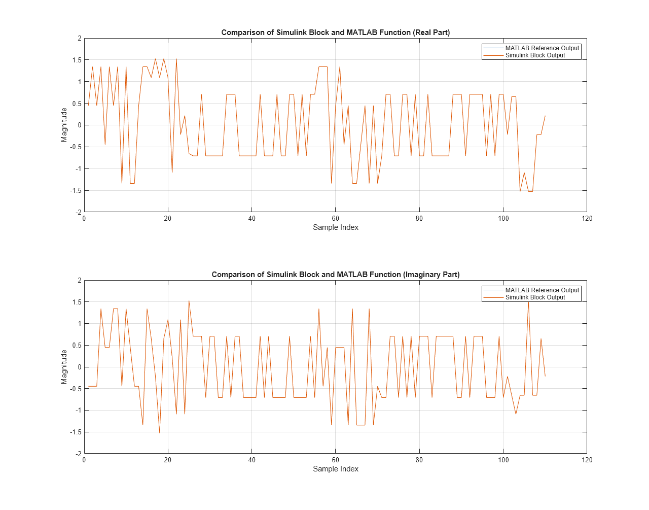
Compare the output of the Symbol Modulator block with the output of the refSymMod function.
referenceOutput = double(cell2mat(referenceOutput.'));
actualData = double(squeeze(modOut(:)));

figure('units','normalized','outerposition',[0 0 1 1])
subplot(2,1,1)
plot(real(referenceOutput(:)));
hold on;
plot(real(actualData(:)));
grid on
legend('MATLAB Reference Output','Simulink Block Output')
xlabel('Sample Index')
ylabel('Magnitude')
title('Comparison of Simulink Block and MATLAB Function (Real Part)')

subplot(2,1,2)
plot(imag(referenceOutput(:)));
hold on;
plot(imag(actualData(:)));
grid on
legend('MATLAB Reference Output','Simulink Block Output')
xlabel('Sample Index')
ylabel('Magnitude')
title('Comparison of Simulink Block and MATLAB Function (Imaginary Part)')

sqnrRealdB = 10*log10(double(var(real(actualData(:)))/abs(var(real(actualData(:)))-var(real(referenceOutput(:))))));
sqnrImagdB = 10*log10(double(var(imag(actualData(:)))/abs(var(imag(actualData(:)))-var(imag(referenceOutput(:))))));

fprintf('\n Symbol Modulator \n SQNR of real part: %.2f dB',sqnrRealdB);
fprintf('\n SQNR of imaginary part: %.2f dB\n',sqnrImagdB);
 Symbol Modulator
 SQNR of real part: 48.53 dB
 SQNR of imaginary part: 47.43 dB