Stereo Fisheye Camera Calibration
Working directly with fisheye images from a stereo camera can be challenging due to their distortion. It is often beneficial to employ a high-quality fisheye camera model, such as the Scaramuzza Model [1], to transform fisheye images into standard images. Although this conversion sacrifices some field of view, it enables the use of standard processing techniques like stereo rectification and disparity computation, which are designed for non-fisheye stereo cameras.
This example shows how to calibrate a stereo fisheye camera using the estimateFisheyeParameters function and the estimateStereoBaseline function.
Overview
Follow these steps to calibrate a stereo fisheye camera by determining each camera's intrinsic parameters and estimating the baseline between them:
Capture Calibration Images: To accurately calibrate your camera, collect 10 - 20 calibration images using the guidelines listed in Prepare Camera and Capture Images for Camera Calibration. This example uses stereo fisheye images from the WPI Lidar Visual SLAM Dataset [2]. The images have been collected using an Intel RealSense T265 camera [3].
Estimate Intrinsic Parameters: Estimate the intrinsic fisheye parameters for each camera. These parameters describe the lens properties of each camera.
Construct Virtual Pinhole Camera: Convert the fisheye camera image to an image as if it was generated using a pinhole camera. This is accomplished by undistorting the central portion of the fisheye image and generating camera intrinsics describing this new virtual camera.
Estimate Baseline: Use the virtual pinhole camera parameters to estimate the baseline of the stereo fisheye camera.
Download Data
Download the calibration images to a folder using the following code.
datasetFolder  = "stereo_fisheye_camera_calibration";
datasetURL  = "https://ssd.mathworks.com/supportfiles/shared_nav_vision/data/";
dataFolder = fullfile("wpi_stereo_visual_slam_dataset");

if ~isfolder(dataFolder)
    mkdir(dataFolder)
end

folderFullPath = fullfile(dataFolder,datasetFolder);
if ~isfolder(folderFullPath)
    fileWithExt = datasetFolder + ".zip";
    zipFilePath = fullfile(dataFolder,fileWithExt);
    disp("Downloading " + fileWithExt + " (46 MB). This download can take a few seconds.")
    websave(folderFullPath,datasetURL + fileWithExt);
    unzip(zipFilePath,dataFolder);
end
Downloading stereo_fisheye_camera_calibration.zip (46 MB). This download can take a few seconds.
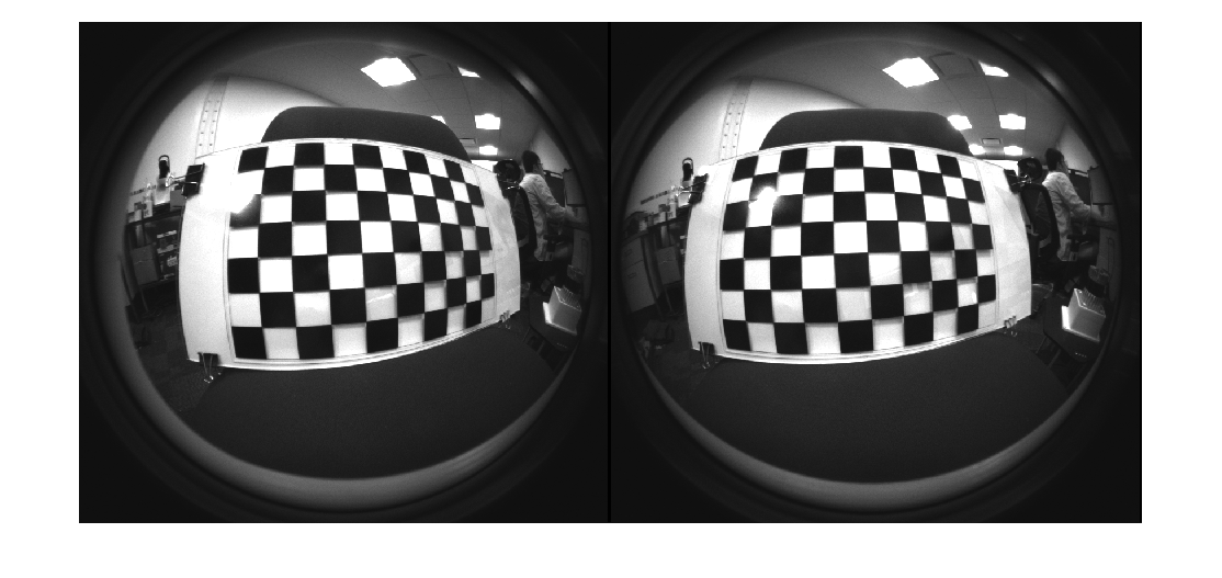
Inspect the first pair of calibration images.
imds1 = imageDatastore(fullfile(folderFullPath, "left"));
imds2 = imageDatastore(fullfile(folderFullPath, "right"));
I1    = readimage(imds1, 1);
I2    = readimage(imds2, 1);
imshowpair(I1, I2, "montage");
Estimate Fisheye Camera Intrinsics
Estimate the intrinsic fisheye parameters of camera 1 and camera 2 independently. Detect the checkerboard keypoints in stereo pairs of images.
[imagePoints, patternDims, pairsUsed] = detectCheckerboardPoints(imds1.Files, imds2.Files, HighDistortion=true);
Generate world coordinates for the checkerboard keypoints.
squareSize  = 40; % millimeters
worldPoints = patternWorldPoints("checkerboard", patternDims, squareSize);
Estimate the fisheye camera calibration parameters using the image and world points.
imageSize    = [size(I1,1) size(I1,2)];
imagePoints1 = imagePoints(:,:,:,1);
imagePoints2 = imagePoints(:,:,:,2);

% Calibrate camera 1
camParams1 = estimateFisheyeParameters(imagePoints1, worldPoints, imageSize);

% Calibrate camera 2
camParams2 = estimateFisheyeParameters(imagePoints2, worldPoints, imageSize);
Construct Virtual Pinhole Camera
Use undistortFisheyePoints function to undistort the detected keypoints and get the camera intrinsics of a virtual pinhole camera corresponding to the undistorted points.
undistortedImagePoints1 = imagePoints1;
undistortedImagePoints2 = imagePoints2;
numImagesUsed           = sum(pairsUsed);
for i = 1:numImagesUsed
    [undistortedImagePoints1(:,:,i), camIntrinsics1] = undistortFisheyePoints(imagePoints1(:,:,i), camParams1.Intrinsics);
    [undistortedImagePoints2(:,:,i), camIntrinsics2] = undistortFisheyePoints(imagePoints2(:,:,i), camParams2.Intrinsics);
end
Estimate Baseline
Estimates the translation and orientation between the two cameras using the virtual camera intrinsics.
undistortedImagePoints = cat(4, undistortedImagePoints1, undistortedImagePoints2);
stereoParams = estimateStereoBaseline(undistortedImagePoints, worldPoints, camIntrinsics1, camIntrinsics2);
The calibrated baseline closely matches the value of 64 mm specified in the camera's datasheet [3].
disp("Calibrated stereo baseline (mm): " + abs(stereoParams.PoseCamera2.Translation(1)));Calibrated stereo baseline (mm): 64.9251
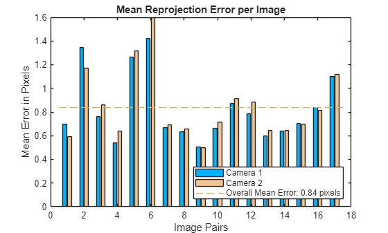
Visualize calibration accuracy.
figure
showReprojectionErrors(stereoParams);
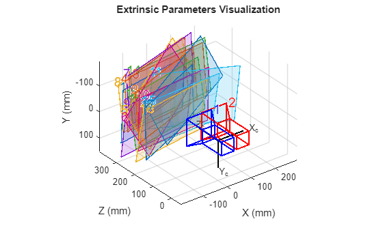
Visualize camera extrinsics.
figure
showExtrinsics(stereoParams);
Rectify Stereo Fisheye Images
After calibrating the stereo fisheye camera, you can rectify the stereo images and compute the disparity as a preprocessing step for 3-D scene reconstruction and stereo visual SLAM.
Remove lens distortion from the first pair of fisheye stereo images and display the results.
J1 = undistortFisheyeImage(I1, camParams1.Intrinsics);
J2 = undistortFisheyeImage(I2, camParams2.Intrinsics);

figure
imshowpair(J1, J2, "montage");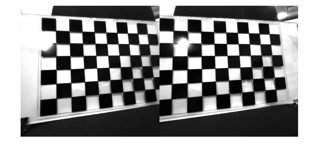
Rectify the undistorted stereo fisheye images.
[J1Full, J2Full, reprojectionMatrix] = rectifyStereoImages(J1,J2,stereoParams);
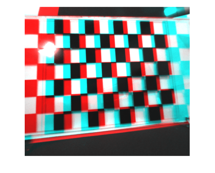
Display the anaglyph image.
figure
imshow(stereoAnaglyph(J1Full, J2Full));
Use the rectified images to compute the disparity map through semi-global matching. Specify the range of disparity as [0, 128], and the minimum value of uniqueness as 10.
disparityRange = [0 128];
disparityMap = disparitySGM(J1Full, J2Full, DisparityRange=disparityRange, UniquenessThreshold=10);
Display the disparity map. Set the display range to the same value as the disparity range.
figure
imshow(disparityMap, disparityRange)
colormap parula
colorbar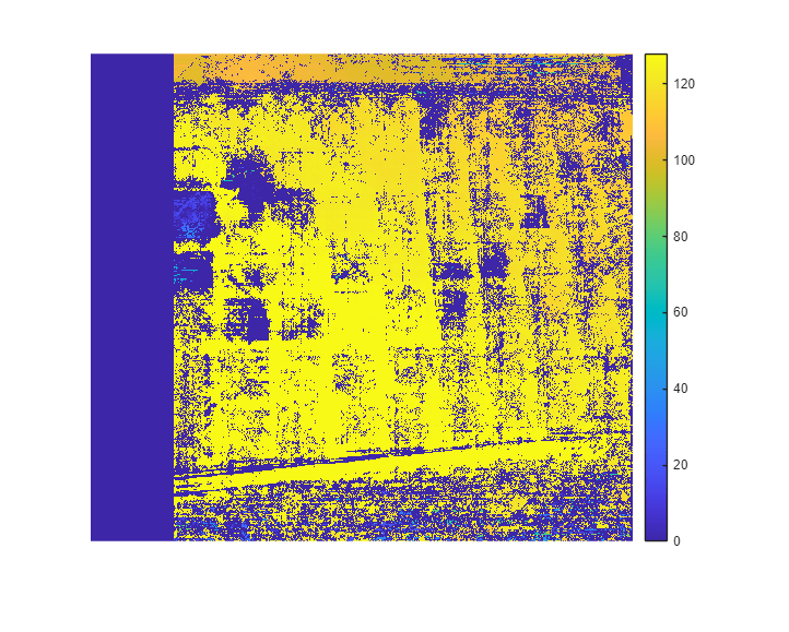
You can find more details about 3-D reconstruction and stereo visual SLAM on the following pages:
References
[1] Scaramuzza, D., A. Martinelli, and R. Siegwart. "A Toolbox for Easy Calibrating Omnidirectional Cameras." Proceedings to IEEE International Conference on Intelligent Robots and Systems (IROS 2006). Beijing, China, October 7–15, 2006.
[2] https://github.com/WPI-APA-Lab/WPI-Lidar-Visual-SLAM-Dataset