Simulate Virtual Vehicle During Braking Maneuver on Highway
To build your virtual vehicle, use the Virtual Vehicle
Composer. After you build your virtual vehicle model, you can change the model
configuration to simulate standard vehicle testing maneuvers and the visualization
environment. This example shows you how to simulate a virtual vehicle model,
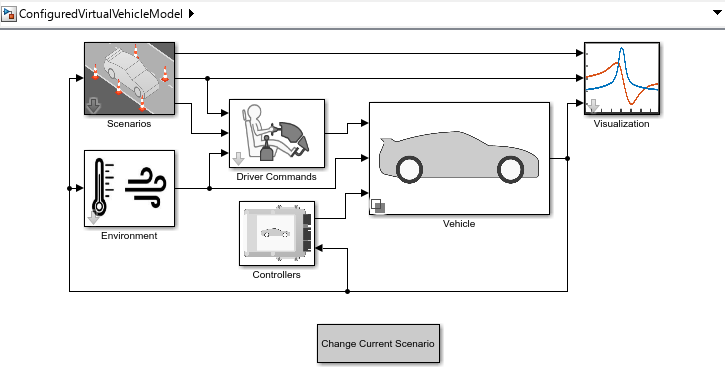
ConfiguredVirtualVehicleModel, in a 3D visualization
environment during a braking maneuver on a highway.
Tip
Before you start, make sure your virtual vehicle is configured with Vehicle
dynamics set to Combined Longitudinal and Lateral
Dynamics.
To configure your virtual vehicle for a braking maneuver, follow these steps.
| Workflow Step | Description |
|---|---|
After you build your virtual vehicle model, change the model configuration to simulate standard testing maneuvers like the braking test. | |
Specify the 3D visualization environment. | |
Specify the maneuver scene and vehicle starting location. In this example, specify a highway scene with vehicle at the recommended starting location. | |
On the |
Step 1: Configure Virtual Vehicle Model
After you build your virtual vehicle model, change the model configuration to simulate
standard testing maneuvers. In this example, update the Scenarios and
Driver Commands subsystems to specify a braking maneuver.
Scenarios
In the configured vehicle model, in Scenarios, select the
Braking variant.
In
ConfiguredVirtualVehicleModel, right-clickScenariosand select Mask > Look Under Mask.Right-click Reference Generator and select Variant > Label Model Active Choice. Select the maneuver. For this example, select Braking. The model implements the Acceleration and Braking block.
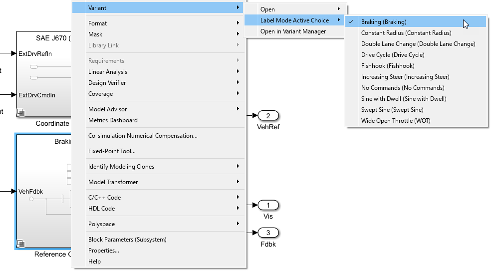
Note
Your configured virtual vehicle model uses the block that corresponds to the maneuver that you select. For example, if you select Double Lane Change, the model implements the Lane Change block.
In
Scenarios, navigate toReference Generator>Drive Cycleand open the Acceleration and Braking block. Click Help to learn more about the parameters. For this example, accept the parameter default values.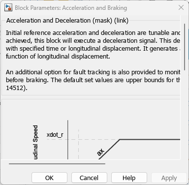
Save
ConfiguredVirtualVehicleModel.
Driver Commands
In the configured vehicle model, in Driver Commands, select the
Longitudinal Driver variant.
In
ConfiguredVirtualVehicleModel, on the Driver Commands block, right-click and select Mask > Look Under Mask.On Driver Commands, right-click and select Variant > Label Model Active Choice. Select the driver. For this example, select Longitudinal Driver. The model implements the Longitudinal Driver block.
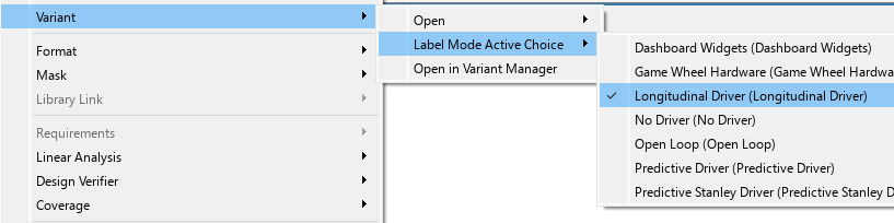
Save
ConfiguredVirtualVehicleModel.
Step 2: Configure 3D Visualization
Update and configure the Visualization and
Environment subsystems for the 3D visualization
environment.
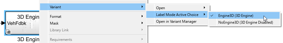
Visualization
In the configured vehicle model, in Visualization, select the
Engine3D variant.
In
ConfiguredVirtualVehicleModel, right-clickVisualizationsand select Mask > Look Under Mask.On 3D Engine, right-click and select Variant > Label Model Active Choice. Select the 3D environment. For this example, select Engine3D to enable 3D visualization.
Save
ConfiguredVirtualVehicleModel.
Environment
In the configured vehicle model, in Environment, select the
3D Terrain variant.
In
ConfiguredVirtualVehicleModel, right-clickEnvironmentand select Mask > Look Under Mask.Right-click
Ground Feedbackand select Variant > Label Model Active Choice. For this example, select 3D Terrain for 3D visualization.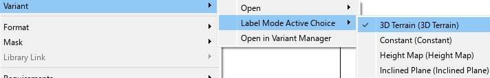
Step 3: Set Scene and Vehicle Starting Location
Specify the maneuver scene and vehicle starting location. In this example, specify a highway scene with vehicle at the recommended starting location. Also specify the scene view.
In the
Visualization>3D Enginesubsystem, open the Simulation 3D Scene Configuration block.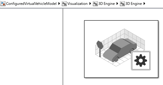
For this example, set these Simulation 3D Scene Configuration block parameters:
Scene name to
US
                                        Highway
Scene view to
SimulinkVehicle1
Click Apply and save the model.
Open the Model Explorer.
In the Model Hierarchy pane, navigate to ConfiguredVirtualVehicleModel > External Data > VirtualVehicleTemplate.
In the list of Referenced Dictionaries, select
PassVeh. Click Open.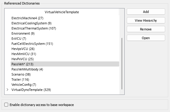
In the Model Hierarchy pane, select ConfiguredVirtualVehicleModel > PassVeh > Design Data.
Set the data dictionary variable value to the initial vehicle position values recommended for the scene. For this example, use these recommended values for the US Highway scene.
Data Dictionary Variable Description Recommended Value PlntVehInitLongPosRecommended starting location - X
3592.00PlntVehInitLatPosRecommended starting location - Y
2617.00PlntVehInitVertPosRecommended starting location - Z
1.00PlntVehInitRollAngRecommended starting location - Roll
0PlntVehInitPitchAngRecommended starting location - Pitch
0PlntVehInitYawAngRecommended starting location - Yaw
0In the
PassVehdata dictionary, confirm the variable values match the recommended starting values for the scene.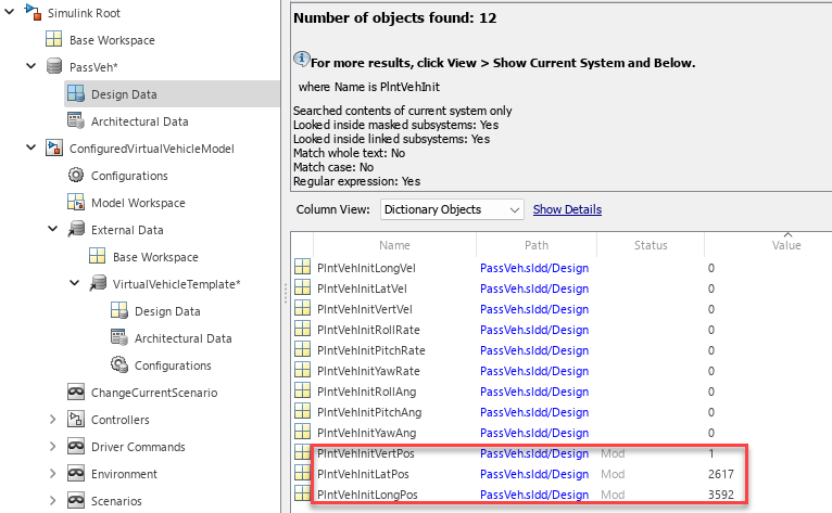
In the Model Explorer, save the
PassVehchanges.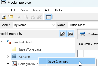
Step 4: Run Simulation
On the ConfiguredVirtualVehicleModel model toolstrip, click
Run. As the simulation runs, view the results in the Simulation
3D Viewer. For this example, view a braking maneuver on a highway.

See Also
Virtual Vehicle Composer | Acceleration and Braking | Longitudinal Driver | US Highway