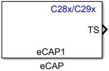
C28x eCAP
Receive and log transitions on capture input pin or configure auxiliary pulse width modulator
Libraries:
C2000 Microcontroller Blockset /
C2802x
C2000 Microcontroller Blockset /
C2803x
C2000 Microcontroller Blockset /
C2805x
C2000 Microcontroller Blockset /
C2806x
C2000 Microcontroller Blockset /
C280x
C2000 Microcontroller Blockset /
C2833x
C2000 Microcontroller Blockset /
C2834x
C2000 Microcontroller Blockset /
F280013x
C2000 Microcontroller Blockset /
F280015x
C2000 Microcontroller Blockset /
F28002x
C2000 Microcontroller Blockset /
F28003x
C2000 Microcontroller Blockset /
F28004x
C2000 Microcontroller Blockset /
F2807x
C2000 Microcontroller Blockset /
F2837xD
C2000 Microcontroller Blockset /
F2837xS
C2000 Microcontroller Blockset /
F2838x /
C28x
C2000 Microcontroller Blockset /
F28M35x /
C28x
C2000 Microcontroller Blockset /
F28M36x /
C28x
C2000 Microcontroller Blockset /
F28p65x
C2000 Microcontroller Blockset /
F28p55x
Description
The eCAP block captures the timing of important external events, such as Hall sensor signals in speed measurements of rotating machinery. When not used in capture mode, the block can be used in APWM mode, which is a single-channel, asymmetric pulse width modulator (APWM). You can add one eCAP block to your model for each capture pin. You cannot assign the same eCAP pin to two eCAP blocks in a model. eCAP and APWM modes use the same pins. In eCAP mode, the pins are used as input to capture the transitions. In APWM mode, the pins are used to output a PWM waveform.
The high resolution mode (HRCAP mode) in eCAP block is available only for specific TI processors. For F2803x and F2806x processors, see HRCAP block.
Examples
Using eCAP Block in HRCAP Mode to Capture Input Signals
Use high resolution mode (HRCAP) in eCAP block to capture the input signals using C2000™ Microcontroller Blockset.
Synchronizing ePWM and eCAP Modules using Time-Base Counter Synchronization
Use time-base counter synchronization in C2000™ Microcontroller Blockset.
Field-Oriented Control of PMSM with Quadrature Encoder Using C2000 Processors
Implements the field-oriented control (FOC) technique to control the speed of a three-phase permanent magnet synchronous motor (PMSM). The FOC algorithm requires rotor position feedback, which is obtained by a quadrature encoder sensor. For details about FOC, see Field-Oriented Control (FOC) (Motor Control Blockset).
Ports
Input
The input from the software used to synchronize the eCAP counter. The synchronization occurs when the synchronization input value is 1.
Dependencies
The port appears only when:
On the General tab, you select Operating mode > eCAP or APWM.
On the General tab, you select Enable counter Sync-In mode and Enable software-forced counter synchronizing input.
Data Types: int8
| uint8
| int16
| uint16
| int32
| uint32
| single
| double
| Boolean
Starts a One-Shot capture sequence.
A 2-bit stop register is used to compare the Mod4 counter output, and when the register and counter values are equal the Mod4 counter is stopped.
Dependencies
The port appears only when:
On the General tab, you select Operating mode > eCAP.
On the eCAP tab, you set Select mode control > One-Shot and select Enable One-Shot re-arming control input.
Data Types: int8
| uint8
| int16
| uint16
| int32
| uint32
| single
| double
| Boolean
Period of the APWM.
Dependencies
The port appears only when:
On the General tab, you select Operating mode > APWM.
On the APWM tab, you select Waveform period source > Input port.
Data Types: int8
| uint8
| int16
| uint16
| int32
| uint32
| single
| double
| Boolean
Width of the APWM.
Dependencies
The port appears only when:
On the General tab, you select Operating mode > APWM.
On the APWM tab, you select Duty cycle source > Input port.
Data Types: int8
| uint8
| int16
| uint16
| int32
| uint32
| single
| double
| Boolean
Output
The output ports appear only in eCAP mode.
TS is a vector of 4 signal dimension corresponding to CAP1, CAP2, CAP3 and CAP4 time stamp values depending on the capture event selected in Stop value after on the eCAP tab. Use the Enable reset counter after capture event # time-stamp option to reset the counter after an event. This option is useful for finding the time difference between the events.
Data Types: int8
| uint8
| int16
| uint16
| int32
| uint32
| single
| double
| Boolean
CF is a vector of dimension 4, corresponds to CEVT1-CEVT2. The status
of the capture event. 0
indicates that no event has
occurred.1
indicates that the event specified by
the Stop value after parameter has occurred
at the eCAP pin.
Dependencies
The port appears only when you select Enable capture event status flag output on the eCAP tab.
Data Types: int8
| uint8
| int16
| uint16
| int32
| uint32
| single
| double
| Boolean
The status of overflow. 0
indicates that counter
has not overflowed.1
indicates that the counter has
overflowed from the highest value to 0.
Dependencies
The port appears only when you select Enable overflow status flag output on the eCAP tab.
Data Types: int8
| uint8
| int16
| uint16
| int32
| uint32
| single
| double
| Boolean
The factor which can be used to convert capture value from HRCLK cycles count to its equivalent SYSCLK cycles count.
Dependencies
The port appears only when you select Enable high resolution capture parameter and set Output type to HRCLK/ SYSCLK cycles on the eCAP tab.
Data Types: single
| double
Parameters
General
When you select eCAP
, the block captures
and logs pin transitions for each capture unit to a FIFO buffer. When
you select APWM
, the block generates
asymmetric pulse width modulation (APWM) waveforms for driving
downstream systems.
Select the required eCAP module to have a dedicated eCAP pin for capturing the external events.
The pin selection for the eCAP module can be done by browsing to Hardware Implementation > Target hardware resources. The selection option is provided only if the module has more than one pin that can be configured for an eCAP module.
This value provides the time base for event captures, clocked by the system clock. A phase register is used to synchronize with other counters via software- or hardware-forced synchronization. For information about software- or hardware-forced synchronization, see Enable counter Sync-In mode parameter. This value is useful in APWM mode when you need a phase offset between capture modules. Set the phase offset to an integer from 0 to 42949667295 (232) counts.
Synchronization can be done using the SYNCI event or the software. When synchronization occurs, the shadow register CTRPHS is loaded into the active counter TSCTR in the current eCAP module and the eCAP modules downstream.
A software method for synchronizing one or more eCAP time bases. The synchronization occurs when the synchronization input value is 1.
Dependencies
This parameter appears only when Enable counter Sync-In mode is selected.
Synchronizes an eCAP counter with other eCAP counters. The options are:
CTR=PRD
— Triggers the sync-out signal when the counter value equals the period.
Pass through
— The sync-in event is passed through as the sync-out signal.Note
Pass through option in case of F2838x/002x and 003x processor is only applicable for
SWSYNC input
.ECAPSYNCIN
signals cannot be passed through and must be configured by the downstream eCAP modules under Hardware Implementation > Target hardware resources > eCAP.Sync output selection of
CTR=PRD
is only applicable for eCAP when Operating mode is set toAPWM
.
Disabled
— Disables the sync-out signal.
Sample time for the block in seconds.
eCAP
To enable configuration parameters on the eCAP tab, set Operating
mode to eCAP
on the
General tab.
The input signal is prescaled by twice the value of this parameter.
For example, if you enter 1
, the input is prescaled
by 2, and for 31
, the input is prescaled by 62.
Entering 0
bypasses the input prescaler, leaving the
input capture signal unchanged.
Select Enable high resolution capture (HRCAP mode) parameter to capture the pulses in high resolution.
Dependencies
This parameter is available only for specific TI processors.
Select Enable continuous calibration mode parameter to perform the calibration periodically.
If continuous calibration mode is not enabled, then calibration occurs only once (Initialization only). High resolution interrupt is used to monitor the status of calibration internally to get the updated scale factor for calculation of time period. Hence Hardware Interrupt block cannot use high resolution interrupt.
Calibration process provides scale factor which is used to calculate high resolution capture values in seconds.
Dependencies
To enable this parameter, select Enable high resolution capture parameter. This parameter is available only for specific TI processors.
Specify the calibration period in seconds.
Dependencies
To enable this parameter, select Enable high resolution capture parameter and Enable continuous calibration mode. This parameter is available only for specific TI processors.
The Continuous
option performs continuous
timestamp captures (events 1 through 4) using a circular buffer.
The One-Shot
option enables the
Enable One-Shot rearming control via input port
option.
When this parameter is selected, a One-Shot capture sequence is re-armed as follows:
Mod4 counter is reset to zero.
Mod4 counter is unfrozen.
Capture register loading is enabled.
Dependencies
This parameter appears only when you select
One-Shot
for Select mode
control.
The number of capture events after which you want to stop the capture sequence.
The eCAP process resets the counter after receiving a capture event
timestamp. In this case, #
represents the number of
the capture event set in the Stop value after
parameter.
The option that starts a capture event. In this case,
#
represents the number of the capture event set
in the Stop value after parameter.
Select the output type for eCAP.
The output type is int the form of HRCLK cycles when used in HRCAP mode (high resolution mode) and SYSCLK when used in normal mode. When you set the output type to HRCLK/SYSCLK cycles in HRCAP mode (high resolution mode), it enables the port Scale factor.
The data type of the timestamp counter.
Outputs the capture event status flag at the output port
CF. The block outputs 0
until the event is captured. After the event, the flag value is
1
.
The data type of the output port CF.
Dependencies
This parameter appears only when you select Enable capture event status flag output.
Outputs the status of the elements of the FIFO buffer at the output port OF.
The data type of the output port OF.
Dependencies
This parameter appears only when you select Enable overflow status flag output.
APWM
To enable configuration parameters on the APWM tab, set Operating
mode to APWM
in the
General tab.
Clock cycles
uses the high-speed peripheral
clock cycles of the processor.
Select Specify via dialog
to enter the
value in Waveform period, or select
Input port
to use a value from the
T input port.
Period of the PWM waveform measured in clock cycles or seconds, as specified in Waveform period units.
Note
The term clock cycles refers to the high-speed peripheral clock on the F2812 chip. This high-speed peripheral clock is 75 MHz by default because the high-speed peripheral clock prescaler is set to 2 (150 MHz/2).
Dependencies
This parameter appears only when Waveform period
source is set to Specify via
dialog
.
The units used for measuring the duty cycle.
Select Specify via dialog
to enter the
value in Duty cycle, or select Input
port
to use a value from the
W input port.
The ratio of PWM waveform pulse duration to PWM waveform period. This ratio is expressed in Duty cycle units.
When you select Active High
, the compare
value (duty cycle) defines the high time. Selecting Active
Low
directs the compare value to define the low
time.
Interrupt
You can use the C28x Hardware Interrupt block to
respond to this interrupt. In this case, #
represents
the number of the capture event set in the Stop value
after parameter.
Dependencies
This parameter appears only when you set Operating
mode to eCAP
in the
General tab.
Triggers an interrupt when the counter overflows.
Dependencies
This parameter appears only when you set Operating
mode to eCAP
in the
General tab.
Posts interrupt when the value of counter is same as the value of the period register (CTR = PRD).
Dependencies
This parameter appears only when you set Operating
mode to APWM
in the
General tab.
Posts interrupt when the value of the counter is same as the value of the compare register (CTR = CMP).
Dependencies
This parameter appears only when you set Operating
mode to APWM
in the
General tab.
MATLAB Command
You clicked a link that corresponds to this MATLAB command:
Run the command by entering it in the MATLAB Command Window. Web browsers do not support MATLAB commands.
Select a Web Site
Choose a web site to get translated content where available and see local events and offers. Based on your location, we recommend that you select: United States.
You can also select a web site from the following list
How to Get Best Site Performance
Select the China site (in Chinese or English) for best site performance. Other MathWorks country sites are not optimized for visits from your location.
Americas
- América Latina (Español)
- Canada (English)
- United States (English)
Europe
- Belgium (English)
- Denmark (English)
- Deutschland (Deutsch)
- España (Español)
- Finland (English)
- France (Français)
- Ireland (English)
- Italia (Italiano)
- Luxembourg (English)
- Netherlands (English)
- Norway (English)
- Österreich (Deutsch)
- Portugal (English)
- Sweden (English)
- Switzerland
- United Kingdom (English)