Design Microcontroller Using the I2C Communication Protocol
This example shows how to design, implement, and test a microcontroller driver to configure and read magnetometer data using the I2C communications protocol. This example progresses through a model-based design cycle, from requirements to code generation.
Open the Project
Open the project from the command line.
i2cstateflow = openProject("i2cstateflow");Opening the project also opens the top model.

Model Architecture and Conventions
The top model consists of three major components:
Compiler provided functions: The compiler for the microcontroller provides a set of high-level functions to interact with the I2C peripheral. Use Simulink® functions to interact with the
magnetometerreference subsystem.Magnetometer: This reference subsystem implements a state machine that replicates the behavior of an I2C peripheral, particularly a magnetometer.
Microcontroller: This reference model implements the necessary state machine in a Stateflow® chart for the peripheral configuration and continuous operation to receive magnetometer readings via I2C.
The microcontroller implements the I2C registers as global data stores via Simulink.Signal objects in the base workspace.
The magnetometer sensor is the HMC5983 Honeywell 3-Axis Digital Compass. The microcontroller is modeled after the Microchip Digital Signal Controller for the dsPIC 33F family.
Simulate the Example
In this example, you can use the Project tab to access requirements, modeling, testing, and code generation.
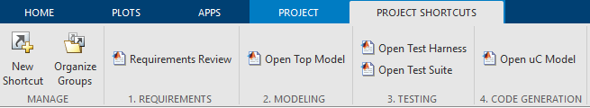
Requirements Review
With the Requirements Toolbox™ you can author, analyze, and manage requirements. As a starting point for this example, review twenty eight functional requirements defined for the I2C driver implementation. To open the requirements set, in the Project Shortcuts tab, click Requirements Review.

These requirements are in two groups:
Device Configuration: These requirements describe the requirements for the magnetometer configuration.
Device Operation: These requirements describe how the model continuously receives the magnetometer readings.
Model Design
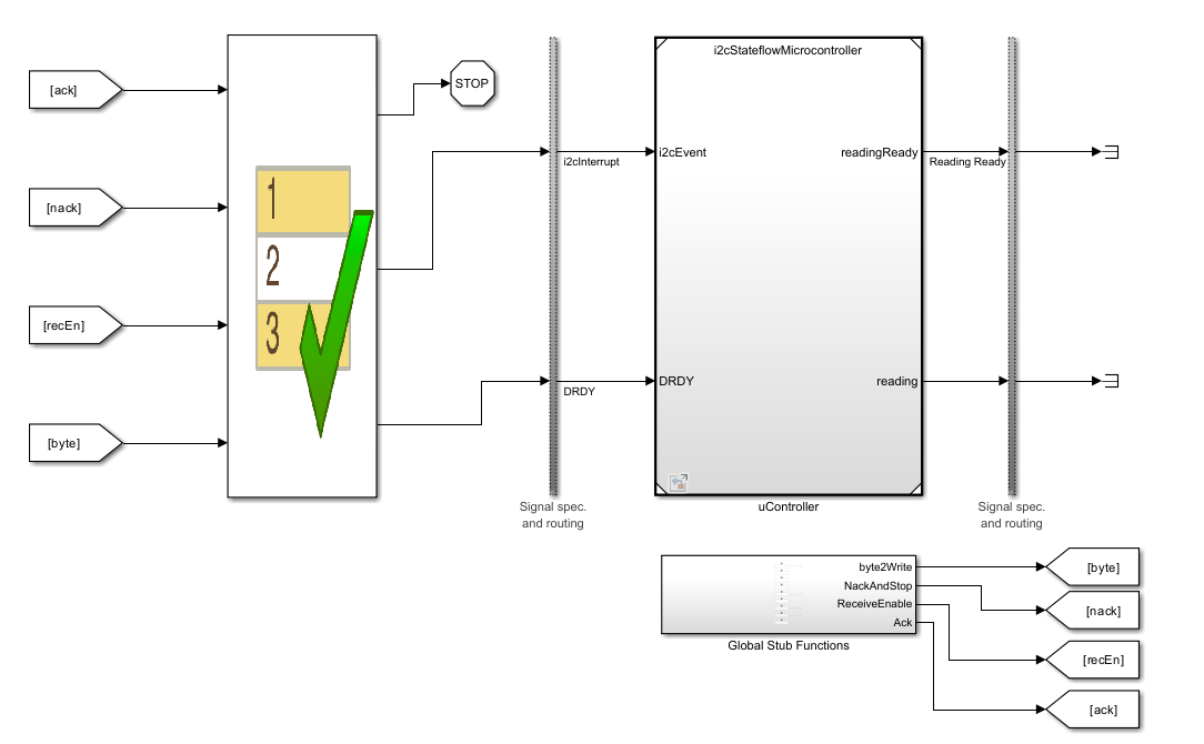
To open the top model, in the Project Shortcuts tab, click Open Top Model. The two key components of the model are the magnetometer and the microcontroller I2C driver.
Magnetometer Model
In the top model, open the magnetometer subsystem to see the magnetometer model. The magnetometer mimics the I2C transactions, as these would happen when interacting with the physical device. It is important to note that this is a logical implementation; this model aims to respond to events in the I2C bus and generate I2C interrupts, which are represented by function calls, instead of representing the actual states of the SDA and SCL lines.

The magnetometer chart receives I2C events in the form of messages. Depending on the current state of the I2C transaction and the microcontroller, the magnetometer generates an I2C function call, a Data Ready function call, or both.
Microcontroller Model
In the top model, open the uController subsystem to see the microcontroller model. The microcontroller model is meant to be used for both, simulation and deployment in a microcontroller as an I2C driver. The objective is for it to design and test the model in simulation and Software-In-the-Loop (SIL), and to generate code for microcontroller deployment.

The event-triggered Driver chart wakes up for every I2C or Data Ready event. At the end of a successful I2C transaction, the readingReady output is 1 and the magReading port contains the 6 bytes corresponding to 2 bytes for each of the X, Y, and Z magnetometer reading. The chart uses functions provided by the microcontroller compiler to interact with the I2C peripheral.
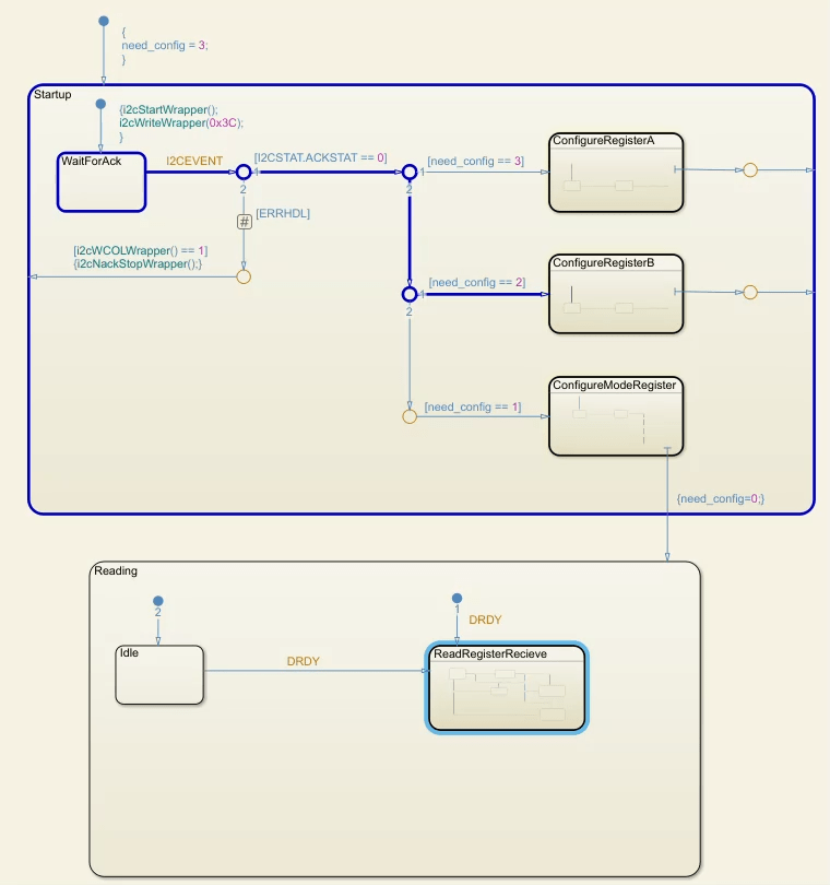
The Driver chart has two parent states: Startup and Reading. While the Startup state is active, the chart goes through the process of configuring the magnetometer registers as established in the requirements. Once the configuration is done, the Reading state becomes active. Every time the chart receives a Data Ready (DRDY) event, it starts a new I2C reading transaction with the magnetometer to get the new reading.

The chart makes use of variant transitions to optionally incorporate error handling when there are bus collisions in the I2C bus.
Examine Links Between Requirements and Model
You can use the Requirements Toolbox to link each individual requirement to the Simulink model component that implements that requirement. Open the i2cStateflowMicrocontroller model.
open_system('i2cStateflowMicrocontroller')After the model opens, enter the Requirements Perspective. Click the Show Perspectives views button in the lower-right corner of the model canvas.

Then click Requirements.

In the Requirements perspective, open the Stateflow chart to see how some of the requirements are implemented.
open_system('i2cStateflowMicrocontroller/Driver')The shaded text boxes show the requirement links between the chart elements and the requirements they implement.

Alternatively, you can navigate from a listed requirement to its implementation. To open the Requirements Editor, in the Project Shortcuts tab, click Requirements Review.
Select a functional requirement and, in the right pane, expand the Links section. The Implemented by section shows the model elements that implement the requirement.
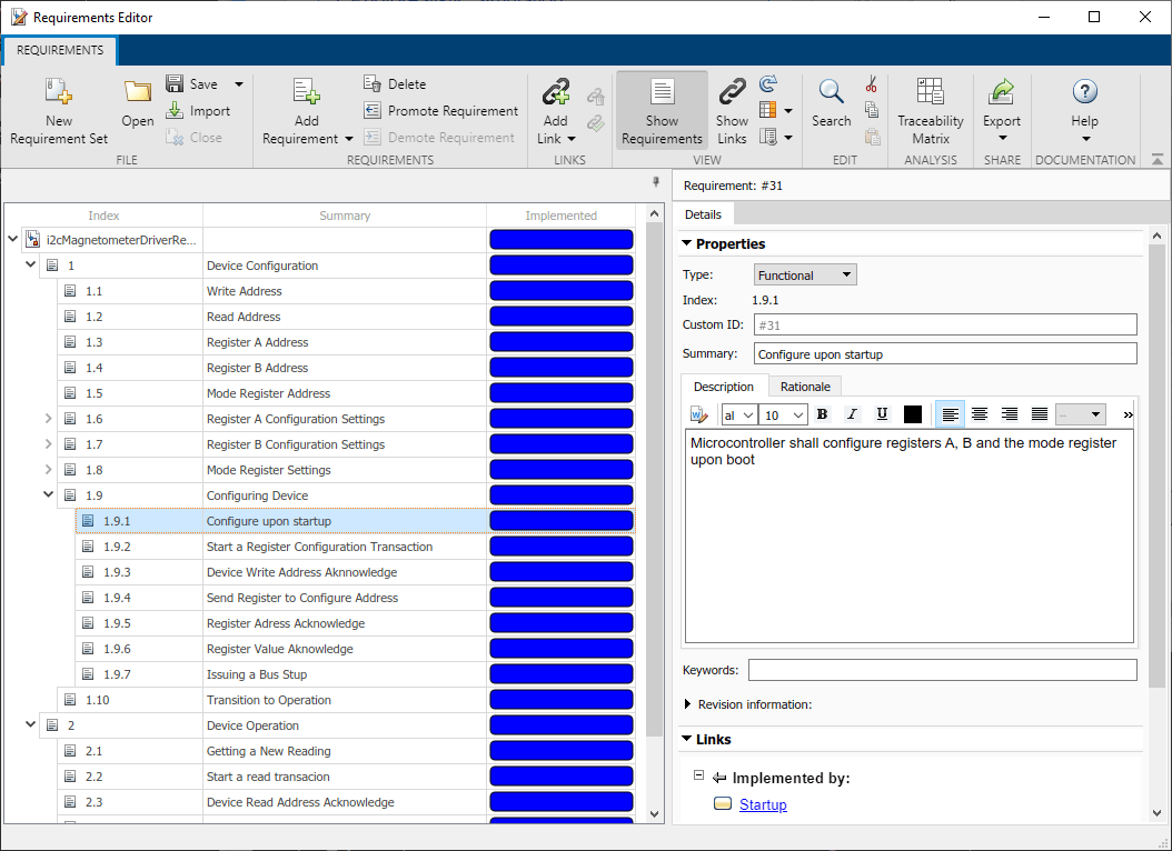
For example, for the above selected requirement, clicking the Startup link takes you to the state that implements this requirement in the Driver chart.
Run the Model
Reopen the top simulation model by clicking the Open Top Model shortcut in the Project Shortcut tab. Click Run. The model runs and completes a few I2C transactions.
To see how the state machine progresses through the transaction:
Open the
Driverchart in thei2cMicrocontrollermodel.From the Debug tab, select Animation Speed dropdown menu, and click
Slow.Run the model.
The model steps through the chart as the peripheral configuration occurs and receives magnetometer readings.
Another way to view how the I2C transaction occurs, is to open the Sequence Viewer at the top model level. In the top model, in the Simulation tab, click Sequence Viewer to open a sequence diagram that shows how the events occur in the simulation. For example, the image below shows the first few interactions between the magnetometer and the microcontroller when performing a sensor reading.

Error Handling
The I2C protocol defines multiple error conditions that can happen during a transaction. This example models two of such errors: a write collision error and an overwrite error. The write collision error happens when two devices try to write at the same time in the bus. This typically happens when two devices try to initiate a transaction at the exact same time. The overwrite error happens when a peripheral sends a byte to the controller device before the controller can read the previous byte and the read buffer is overwritten.
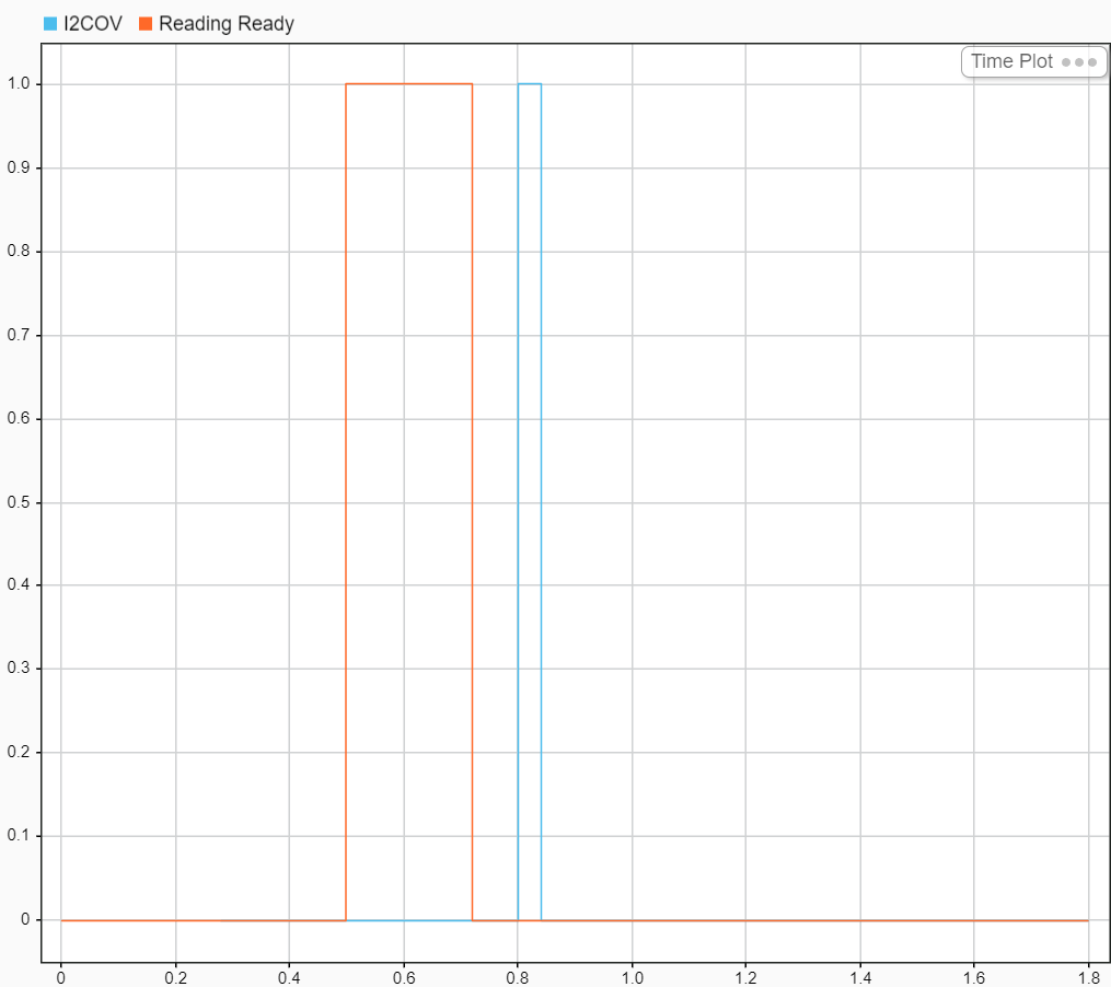
To see what can happen when there is no error handling, disable the error handling variant transitions in the Driver chart and enable the block that creates the error conditions.
ERRHDL.Value = false;
ERRGEN.Value = true;
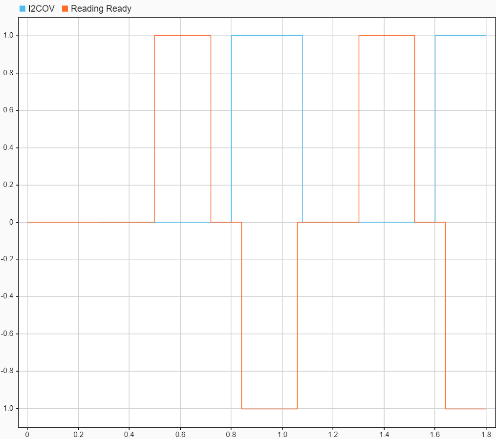
Run the simulation. After the successfully receiving the first magnetometer reading (readingReady), an overwrite error occurs (I2COV). The device never recovers from this error condition and does not receive any other readings.
Now enable the error handling for variant transitions.
ERRHDL.Value = true;
With error handling enabled, the model recovers from error and continues receiving sensor readings.
Disable error handling.
ERRHDL.Value = false;
ERRGEN.Value = false;
Test the Model
This example includes a test harness and a Simulink Test™ test suite that tests the behavior of the Driver chart.
Test Harness
The test harness is an independent model that progresses the chart through the Startup and Reading states and verifies that the chart makes the correct I2C functions calls as it conducts I2C transactions.
To open the test harness, in the Project Shortcuts tab, click Open Test Harness.
The Test Sequence block contains eight different scenarios. Seven of the scenarios progressively test more sections of the Driver chart. The first scenario tests a complete sequence from power up to complete sensor reading. Each scenario uses verify statements to ensure that the chart progresses as expected.

Test Suite
This example includes eight tests that automate testing the model to verify each of the requirements are met. To see how these tests are implemented, click the Open Test Suite shortcut in the Project Shortcut tab. This opens the test suite in the Test Manager. Each test is responsible to verify a subset of the requirements are met by running the test harness on a given Test Sequence scenario. If all verify statements are true, the test passes.
To run the complete test suite, select i2cMagnetometerDriverTests in the test browser, and click the Run. All tests pass.

Requirement Validation
As a final step in testing the model, open the Requirements Editor by clicking the Requirements Review project shortcut and select Implementation Status and Validation Status from the toolstrip.

The Requirements Editor shows that the tests are implemented and verified.

Generate Code
Next, generate code for the Driver chart to deploy to an embedded system.
Open the microcontroller model. In the Project Shortcuts tab, click Open uC Model.
In the Apps tab, click Embedded Coder.
In the C Code tab, click Generate Code.
The generated code has 3 entry point functions.
void i2cStateflowMicrocontroller_initialize(void): This function initializes the necessary variables and the state machine. This function should be called once after device startup.void DRDY(void)andvoidi2cEvent(void): Call these functions when either an Data Ready or a I2C interrupts are triggered.
See Also
Create Custom Simulink Toolstrip Tabs (Simulink)