Model a Wind Turbine Supervisory Control System
This example shows how you can use Stateflow® to model a supervisory control system that uses data from the wind speed and the state of the power grind to determine how to operate a wind turbine. You examine a Stateflow chart that manages the operational modes for the wind turbine and detects potential faults.
To ensure reliability and safety of wind turbine operations, the chart implements specific states for fault management and recovery. Additionally, you can generate PLC Code for the Turbine State Machine chart. For more information on generating PLC Code, see Generate and Examine Structured Text Code (Simulink PLC Coder).
Model Systems
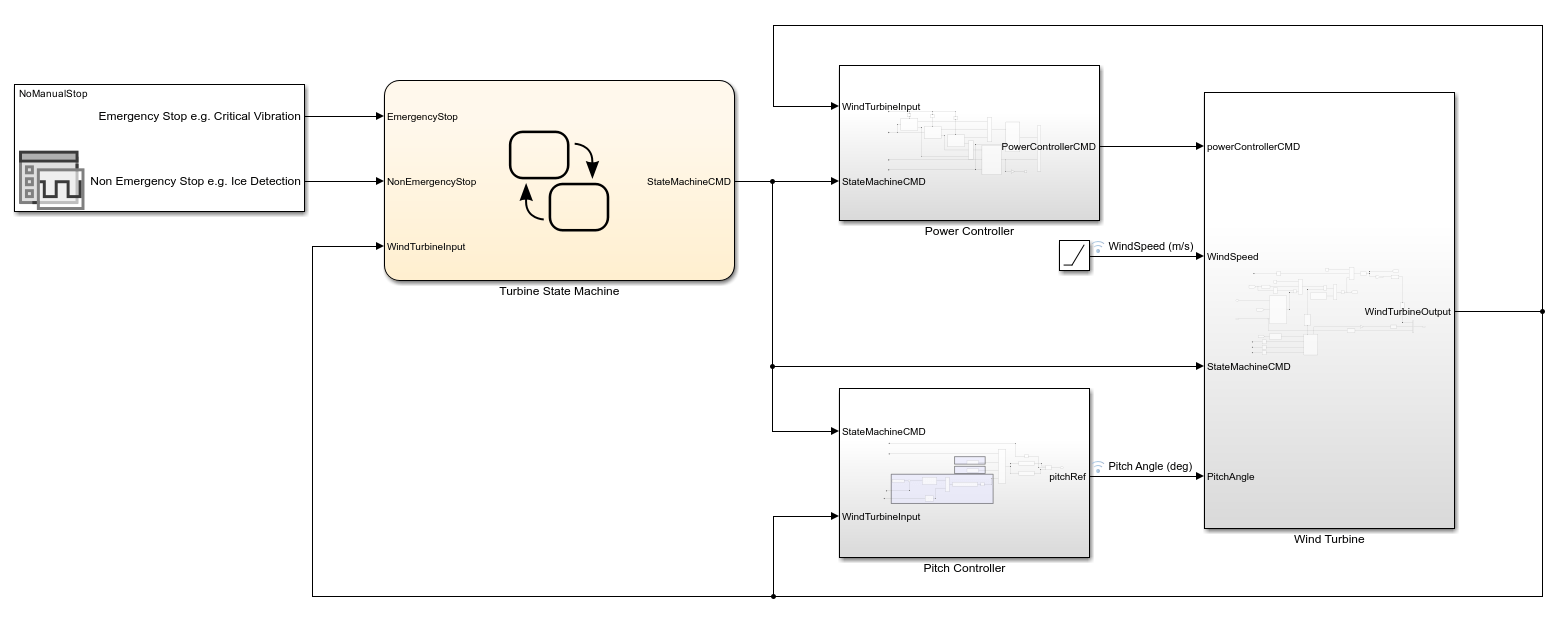
This model contains a Signal Editor block that configures the input signals, a Stateflow chart, and three subsystems:
Power Controllermanages the power output of the turbine.Pitch Controlleradjusts the blade angle to optimize efficiency.Wind Turbinerepresents the physical characteristics and dynamics of the turbine.
The Stateflow chart, Turbine State Machine, controls the modes of operation for power generation. If the chart detects any faults, it forces the wind turbine to stop and stabilize before resuming power generation.
Wind Turbine Control System
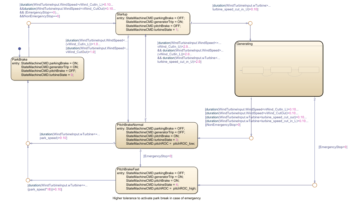
Inside the Turbine State Machine subchart, the default state is ParkBrake. This state forces the wind turbine to remain immobile when not in operation.
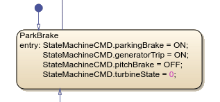
When the Stateflow chart is in this mode of operation, the parking brake and generator trip, represented by the parkingBrake and generatorTrip data, respectively, are ON. The pitch brake is OFF, and the turbine state is 0. The generator trip disconnects the generator from the electrical grid, and the turbine blades are not locked at a specific angle because the pitch brake is off.
When the wind speed from the turbine is greater than the lower windspeed threshold, cutin_L, and less than the upper wind speed threshold, cutout, for over 0.10 seconds, and all stops are clear, the chart transitions to the Startup state.
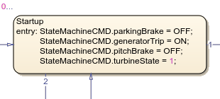
In this state:
The parking break is
OFF.The generator trip is
ON.The pitch break remains
OFF.
These settings allow the generator to prioritize achieving a stable rotation speed before it connects to the electrical grid and begins generating power.
If the angular frequency, wTurbine, of the wind turbine is greater than upper turbine speed threshold, turbine_speed_cut_in_U, for more than 0.10 seconds, the chart transitions to the Generating state. However, if the wind speed from the turbine is greater than the lower windspeed threshold, cutin_L, and greater than the upper wind speed threshold, cutout, for 1 second, the chart transitions to the PitchBrakeNormal state.
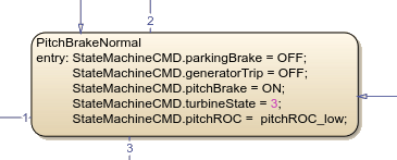
In the PitchBrakeNormal state, the parking break is OFF, the generator trip is OFF, the pitch break is ON, and the rate of change for the blade angle, pitchROC, is low. The chart activates this state when the turbine needs to slow down due to high wind speeds or other safety concerns, but a complete stop is not immediately necessary. This state prioritizes controlled deceleration.
From PitchBreakNormal, the chart can transition to these states:
ParkBrakeStartupPitchBrakeFast
The PitchBrakeFast state represents an emergency response mode that rapidly decelerates the turbine blades. The chart transitions to this state when the system detects an emergency stop condition, which occurs when the value of the EmergencyStop variable exceeds 0. This data represents signals a critical situation that requires immediate action.
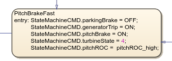
This state prioritizes rapid deceleration by employing aggressive blade pitching and isolating the generator from the grid. This combination of actions aims to bring the turbine to a safe operating speed, and minimize the risk of damage or accidents.
Energy Generation Operation Modes
The Generating subchart includes three child states:
MPPT: Models a state of maximum power point trackingConstSpeed: Models a state of constant turbine speedConstPower: Models a state of constant power output

In this subchart, the parking brake,generator trip, and the pitch brake are off. The default child state is MPPT.
The MPPT state continuously fine-tunes the blade pitch, so that the turbine can adapt to fluctuating wind speeds. These adjustments allow the turbine to maximize energy production.
When the wind speed is greater than the maximum speed rating for the wind turbine, vWind_MaxGenSpeed_U, the chart transitions to the ConstSpeed state.
When the wind speed causes a greater power output than the maximum power rating for the wind turbine, vWind_RatedPower_U, the chart transitions to the ConstPower state to prevent overloading the electrical system.
Simulate the Model
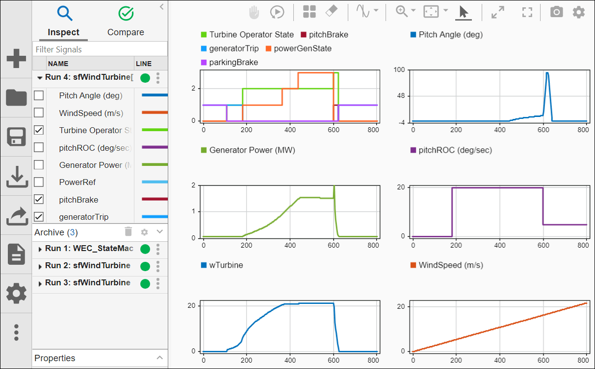
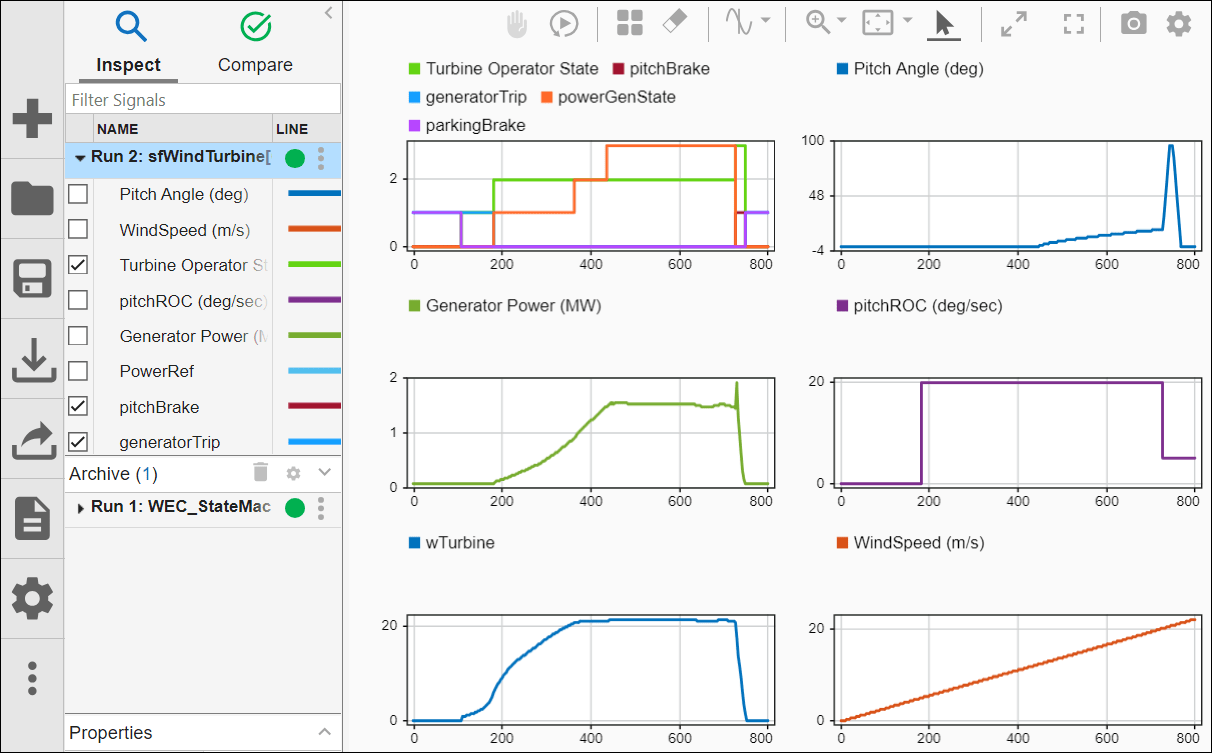
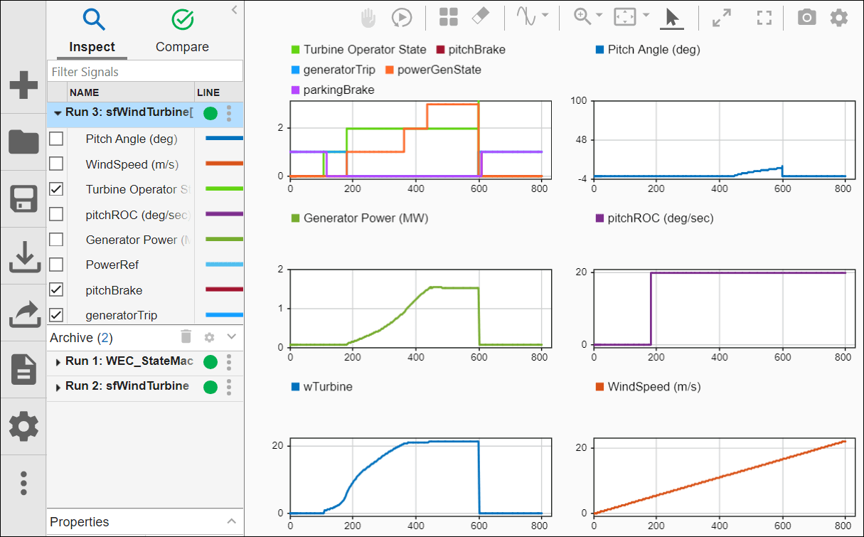
To simulate the model, click Run. After simulation, use Simulation Data Inspector to view the results. For more information about configuring your Simulation Data Inspector graphs, see Inspect Simulation Data (Simulink). The results show data for the NoManualStop scenario.
The top left graph shows how the Generating state changes operating mode through the simulation, and how the operating mode corresponds to the settings for pitchBrake, generatorTrip, and parkingBrake.
When you change the scenario to ManualStop_EmergencyStop, this is the result:
When you change the scenario to ManualStop_NonEmergencyStop, this is the result: