Model a Car with Automatic Transmission
This example uses a Stateflow® chart to model the control logic for the automatic transmission of a car.
![]()
The model has these components:
The
InputsSignal Editor block selects theCoasting,Gradual_Acceleration,Hard_braking, orPassing_Maneuverdriving scenarios. Based on the scenario, the block outputs different brake and throttle data to the model.The
shift_logicchart controls the active gear of the automatic transmission.The
Engine,transmission, andVehiclesubsystems model the mechanical operation of the car.
Model the Automatic Transmission
In the shift_logic chart, the state gear_state models a four-speed automatic transmission.
![]()
When gear_state receives an UP event, it switches to a higher gear. When it receives a DOWN event, it switches to a lower gear. To share this data with the rest of the model, the chart assigns the active child of gear_state to the output data gear.
The state selection_state operates in parallel with gear_state. As the speed of the car changes, selection_state moves between the downshifting, upshifting, and steady_state operating modes. On each step, a during action assigns new upshift and downshift thresholds to the local data down_th and up_th by using the Simulink function calc_th.
To prevent rapid toggles between upshifting and downshifting, selection_state does not broadcast events until the number of time steps specified by the TWAIT parameter elapse. If the car no longer meets the upshifting or downshifting threshold before this number of time steps, the chart returns to steady_state. Otherwise, selection_state broadcasts an UP or DOWN event to gear_state.
Output the Active Child of a State
The output data gear contains the name of the active child of the state gear_state. As the active child changes, so does the value of gear.
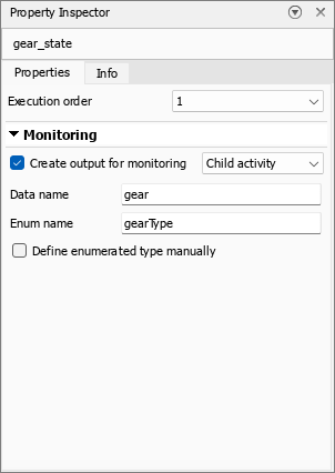
To see the output data settings for gear_state, select the state. In the Modeling tab, click Property Inspector. In this example, Create output for monitoring is selected, Data name is gear, and Enum name is gearType. These settings create an enumerated output data named gear that uses the names of the child states as values. The enumeration has the type gearType.
Call Simulink Function from a State or Transitions
On each step, the selection_state state calls the calc_th Simulink function to calculate new upshifting and downshifting thresholds in response to changes in the gear and throttle.
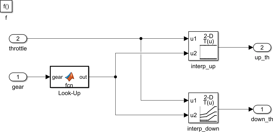
The calc_th function calculates new thresholds by sending the throttle and gear data to two Lookup Table (n-D) blocks.
Simulate the Model
The model logs the value of the engine RPM, throttle, and vehicle speed signals in the Simulink Data Inspector.
To simulate the model, in the Simulation tab, click Run.
To open the Simulink Data Inspector, in the Simulation tab, click Data Inspector.
To display results, in the left pane, click the check boxes next to each signal. For information on displaying multiple plots, see Select Plot Layout (Simulink).
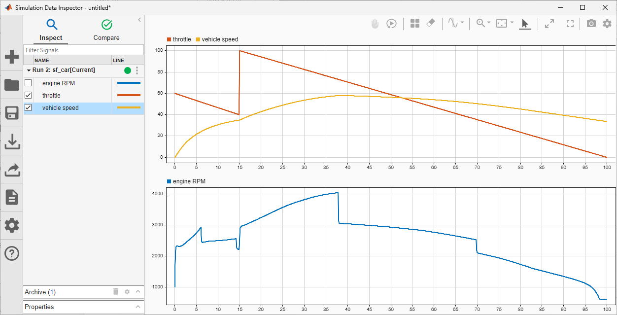
As the throttle changes, the car accelerates or decelerates. When the car crosses certain speed thresholds, the automatic transmission upshifts or downshifts, and the engine RPM rapidly raises or lowers.