spsConversionAssistant
Convert Specialized Power Systems model into Simscape Electrical model
Since R2025b
Syntax
Description
Note
For more information about upgrading Specialized Power Systems models, see Upgrade Specialized Power Systems Models to use Simscape Electrical Blocks.
spsConversionAssistant tries to replace the Specialized Power
Systems library blocks in the currently open model with Simscape™
Electrical™ library blocks, while preserving the parameter values and connections between
blocks. The function saves the converted model in the same folder as the original model and
generates an HTML report that lists the fully supported, partially supported, and
unsupported blocks. The file name of the converted model is the original model name with
_simscape appended to the end.
After the conversion finishes, review the replaced blocks and manually convert the unsupported blocks to Simscape and Simscape Electrical blocks.
spsConversionAssistant( converts the
blocks in the model, modelName)modelName. The model must be loaded or on your
MATLAB® search path. Alternatively, specify the modelName
argument as a character vector or string scalar that contains an absolute or relative path
name.
spsConversionAssistant(
saves the converted model in the specified folder, modelName,outputFolder)outputFolder. The
function creates the folder if it does not exist.
writable = spsConversionAssistant(___)1 if the file and folder permissions allow the function to save
the converted model. Otherwise, this function returns 0.
Examples
This example shows you how to convert fully supported and partially
supported Specialized Power Systems library blocks in a model to Simscape
Electrical library blocks by using the spsConversionAssistant
function. In this example, you first open the original model and add signal logging to all
scope inputs. Then, you run a simulation of the original model to obtain the logged
results and perform the conversion using the spsConversionAssistant
function. Finally, you run the converted model and compare the output of both models.
Note
To run this example, replace "myModelName" with the name of the
original model that you want to convert.

Specify the name of the original model you want to convert and open the model.
originalModelName = "myModelName";
open_system(originalModelName);
To capture all relevant data during the simulation, add signal logging to all the
scope inputs in the model. To find all Scope blocks in the model, use the
find_system function and set the BlockType
input argument to "Scope". Mark the input signals of these
blocks for logging.
If the original model does not contain any Scope blocks, to help confirm the conversion process, add Scope blocks to the model and connect them to signals of significant interest.
scopes = find_system(originalModelName,BlockType="Scope");
for scopeIdx = 1:height(scopes)
    thisScope = scopes{scopeIdx};
    lines = get_param(thisScope,"LineHandles");
    lines = lines.Inport;
    for lineIdx = 1:length(lines)
        thisLine = lines(lineIdx);
        Simulink.sdi.markSignalForStreaming(thisLine,"on");
    end
end
To retain these changes, save the updated model.
save_system(originalModelName);
Log results by running a simulation of the original model.
sim(originalModelName);
Use the spsConversionAssistant function to replace the
Specialized Power Systems blocks in the model with Simscape
Electrical blocks.
spsConversionAssistant(originalModelName);
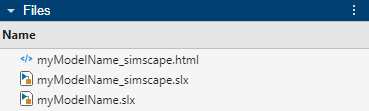
The function creates a new file named myModelName_simscape and
saves it and the conversion HTML report in the current folder.
Review the HTML report, inspect replaced blocks for correctness, and manually convert unsupported blocks to Simscape and Simscape Electrical blocks.
Open the converted model.
convertedModelName = originalModelName+"_simscape";
open_system(convertedModelName);
Log results by running the converted Simscape model.
sim(convertedModelName);
Compare the outputs of the original and converted models. This comparison helps you identify any discrepancies between the two sets of results. Consider setting the absolute and relative tolerances to values that make sense for your model.
absoluteTolerance = 1e-3;
relativeTolerance = 0.01;
timeTolerance = 1e-3;
runIDs = Simulink.sdi.getAllRunIDs;
runDiff = Simulink.sdi.compareRuns(runIDs(end-1,1),runIDs(end,1),...
            abstol=absoluteTolerance,...
            reltol=relativeTolerance,...
            timetol=timeTolerance);
Visualize the differences between the original and converted model outputs. The visualization shows the tolerances so you can observe if the differences are within these tolerances. This step provides a clear view of how the models compare and highlights any significant variations in their behavior.
Simulink.sdi.view(Simulink.sdi.GUITabType.CompareRuns);
If the original and converted model outputs are considerably different, further investigate the model to determine whether the discrepancies are acceptable. If the differences occur at the start of the simulation, they might be caused by initialization differences. If you observe differences in other signals, review the HTML report to determine whether they result from converted blocks that are only partially supported.
Input Arguments
Output Arguments
Tips
To minimize differences between the simulation results of the original and converted models, try resolving the simulation warnings in your original model before the conversion. For more information about simulation errors and warnings, see Systematic Diagnosis of Errors and Warnings.
You can also try to minimize differences between the simulation results of the original and converted models by tightening the solver tolerances. To specify the solver tolerances, open the Configuration Parameters dialog box. In the Simulink® Editor, on the Modeling tab, click Model Settings. In the Configuration Parameters dialog box, click the Solver pane and expand the Solver Details section. Set the Relative tolerance and Absolute tolerance parameter values to
1e-3or1e-4. Do not set these parameters toauto. For more information, see Solver Pane.If your original model contains controllers with direct feedthrough, the converted model might exhibit algebraic loops. Consider measurement filtering, including using low-pass filters or introducing sensor latency, and actuation delays to try to avoid algebraic loops in the simulation.
In Simscape, you are not required to specify an on-state inductance parameter for switches. You might be able to eliminate snubber circuits from your original model, as Simscape handles ideal switching events without additional snubber components to aid numerical convergence.
When you simulate the converted model, the initialization values at time 0 might be different than in your original model. To improve initialization behavior and get the initialization values at time 0 closer to the initialization values of the original model, review the initial target values in your blocks and specify appropriate steady-state values. For more information about initial targets, see Set Priority and Initial Target for Block Variables.
During the simulation, timing jitter might occur in switching events, especially in models that use pulse-width modulation (PWM) signals in closed-loop control systems. As a result, instantaneous signal values might differ between models. When you evaluate the conversion results, focus on the peak and averaged signal values instead. Minor discrepancies due to timing jitter are expected and do not typically impact the overall model behavior. However, if you observe significant differences in peak or averaged values, review the model for initialization differences and partially supported or unsupported conversions.
Select
ode23tordaesscas the solver for your converted model. For more information about solvers in physical models, see Making Optimal Solver Choices for Physical Simulation.If your original model uses a continuous solver, the converted model might generate different results due to the solver configuration. To help remove issues with the solver configurations and obtain comparable results:
Set the Simulation type parameter of the powergui block in your original model to
Discrete.In the Solver Configuration block of your converted model, select the Use local solver parameter.
Specify the same value for both the Sample time (s) parameter in the powergui block of the original model and the Sample time parameter in the Solver Configuration block of the converted model.
Version History
Introduced in R2025b