Nonlinear Transformer
Transformer with nonideal core
Libraries:
Simscape /
Electrical /
Passive /
Transformers
Description
The Nonlinear Transformer block represents a transformer with a nonideal core. A core may be nonideal due to its magnetic properties and dimensions. The equivalent circuit topology depends upon the option you choose to parameterize the winding leakage.
If you set Winding parameterized by to Combined primary
and secondary values
, you use lumped resistance and inductance values to
represent the combined leakage in the primary and secondary windings.
In this diagram:
Req is the combined winding resistance.
Leq is the combined leakage inductance.
L2 is the secondary leakage inductance.
Rm is the magnetization resistance.
Lm is the magnetization inductance.
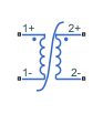
If you set Winding parameterized by to Separate primary
and secondary values
, you use separate resistances and inductances to
represent leakages in the primary and secondary windings.
In this diagram:
R1 is the primary winding resistance.
L1 is the primary leakage inductance.
R2 is the secondary winding resistance.
L2 is the secondary leakage inductance.
Rm is the magnetization resistance.
Lm is the magnetization inductance.
To parameterize the nonlinear magnetization inductance, set the Magnetization inductance parameterized by parameter to one of these options:
Single inductance (linear)
Single saturation point
Magnetic flux versus current characteristic
Magnetic flux density versus magnetic field strength characteristic
Magnetic flux density versus magnetic field strength characteristic with hysteresis
For more information about these parameterization options including the equations that the block uses to model nonlinear magnetization inductance, see the Nonlinear Inductor block reference page.
Simscape™ and Simscape Electrical™ libraries include several blocks than can model the same type of transformer device. However, these blocks make different modeling assumptions. To choose the right block for your application, you must understand how these assumptions impact the block behavior as a function of frequency. For more information, see Choose Blocks to Model Transformers.
Examples
Nonlinear Transformer Characteristics
Calculation and confirmation of a nonlinear transformer core magnetization characteristic. Starting with fundamental parameter values, the core characteristic is derived. This is then used in a Simscape™ model of an example test circuit which can be used to plot the core magnetization characteristic on an oscilloscope. Model outputs are then compared to the known values.
Three-Phase High-Power Converter Design and Analysis Workflow
The main steps involved in designing a high-power converter. High power converters are important building blocks for future electric mobility and microgrid solutions. To design a cost effective, lightweight, efficient converter, you must perform detailed analysis of different converter design options and deployment scenarios. This example helps you to simulate the steady state, transient electrical, and thermal characteristics of a three-phase two-level converter that uses Insulated-Gate Bipolar Transistor (IGBT) devices.
Ports
Conserving
Electrical conserving port associated with the primary winding positive polarity.
Electrical conserving port associated with the primary winding negative polarity.
Electrical conserving port associated with the secondary winding positive polarity.
Electrical conserving port associated with the secondary winding negative polarity.
Parameters
Main
Number of turns of wire on the primary winding of the transformer.
Number of turns of wire on the secondary winding of the transformer.
Parameterization option for winding leakage. Choose one of these methods:
Combined primary and secondary values
— Use the lumped resistance and inductance values to represent the combined leakage in the primary and secondary windings.Separate primary and secondary values
— Use separate resistances and inductances to represent leakages in the primary and secondary windings.
Lumped equivalent resistance Req, which represents the combined power loss of the primary and secondary windings.
Dependencies
To enable this parameter, set Winding parameterized by to
Combined primary and secondary values
.
Lumped equivalent inductance Leq, which represents the combined magnetic flux loss of the primary and secondary windings.
Dependencies
To enable this parameter, set Winding parameterized by to
Combined primary and secondary values
.
Resistance R1, which represents the power loss of the primary winding.
Dependencies
To enable this parameter, set Winding parameterized by to
Separate primary and secondary values
.
Inductance L1, which represents the magnetic flux loss of the primary winding.
Dependencies
To enable this parameter, set Winding parameterized by to
Separate primary and secondary values
.
Resistance R2, which represents the power loss of the secondary winding.
Dependencies
To enable this parameter, set Winding parameterized by to
Separate primary and secondary values
.
Inductance L2, which represents the magnetic flux loss of the secondary winding.
Dependencies
To enable this parameter, set Winding parameterized by to
Separate primary and secondary values
.
Averaging period for power logging.
Magnetization
Resistance Rm, which represents the magnetic losses in the transformer core.
Select one of the following methods for the nonlinear magnetization inductance parameterization:
Single inductance (linear)
— Provide the unsaturated inductance value.Single saturation point
— Provide the values for the unsaturated and saturated inductances, as well as saturation magnetic flux.Magnetic flux versus current characteristic
— Provide the current vector and the magnetic flux vector, to populate the magnetic flux versus current lookup table.Magnetic flux density versus field strength characteristic
— Provide the values for effective core length and cross-sectional area, as well as the magnetic field strength vector and the magnetic flux density vector, to populate the magnetic flux density versus magnetic field strength lookup table.Magnetic flux density versus field strength characteristic with hysteresis
— In addition to the number of turns and the effective core length and cross-sectional area, provide the values for the initial anhysteretic B-H curve gradient, the magnetic flux density and field strength at a certain point on the B-H curve, as well as the coefficient for the reversible magnetization, bulk coupling coefficient, and inter-domain coupling factor, to define magnetic flux density as a function of both the current value and the history of the field strength.
Inductance when the magnetization inductance Lm operates in its linear region.
Dependencies
To enable this parameter, set Magnetization inductance parameterized
by to Single inductance (linear)
or
Single saturation point
.
Inductance when the magnetization inductance Lm operates beyond its saturation point.
Dependencies
To enable this parameter, set Magnetization inductance parameterized
by to Single saturation point
.
Magnetic flux at which the magnetization inductance Lm saturates.
Dependencies
To enable this parameter, set Magnetization inductance parameterized
by to Single saturation point
.
Current data that the block uses to populate the magnetic flux versus current lookup table.
Dependencies
To enable this parameter, set Magnetization inductance parameterized
by to Magnetic flux versus current
characteristic
.
Magnetic flux data that the block uses to populate the magnetic flux versus current lookup table.
Dependencies
To enable this parameter, set Magnetization inductance parameterized
by to Magnetic flux versus current
characteristic
.
Magnetic field intensity H, specified as a vector with the same number of elements as the magnetic flux density vector B.
Dependencies
To enable this parameter, set Magnetization inductance parameterized
by to Magnetic flux density versus field strength
characteristic
.
Magnetic flux density B, specified as a vector with the same number of elements as the magnetic field strength vector H.
Dependencies
To enable this parameter, set Magnetization inductance parameterized
by to Magnetic flux density versus field strength
characteristic
.
Effective core length. This parameter represents the average length of the magnetic path around the core.
Dependencies
To enable this parameter, set the Magnetization inductance parameterized
by parameter to Magnetic flux density versus field
strength characteristic
or Magnetic flux density
versus field strength characteristic with hysteresis
.
Effective core cross-sectional area. This parameter represents the average area of the magnetic path around the core.
Dependencies
To enable this parameter, set the
Magnetization inductance parameterized
by parameter to Magnetic
flux density versus field strength
characteristic
or
Magnetic flux density versus field
strength characteristic with
hysteresis
.
Gradient of the anhysteretic B-H curve around zero field strength. Set this parameter to the average gradient of the ascending and descending hysteresis curves.
Dependencies
To enable this parameter, set the Magnetization inductance parameterized
by parameter to Magnetic flux density versus field
strength characteristic with hysteresis
.
Flux density of the point for field strength measurement. You must specify a point on the anhysteretic curve by providing its flux density value. To obtain accurate results, pick a point at high field strength where the ascending and descending hysteresis curves align.
Dependencies
To enable this parameter, set the Magnetization inductance parameterized by parameter to Magnetic flux density versus field strength characteristic with hysteresis
.
Field strength that corresponds to the point that you define using the Flux density point on anhysteretic B-H curve parameter.
Dependencies
To enable this parameter, set Magnetization inductance parameterized by to Magnetic flux density versus field strength characteristic with hysteresis
.
Coefficient for reversible magnetization in the Jiles-Atherton equations, c. This parameter represents the proportion of the magnetization that you can reverse.
Dependencies
To enable this parameter, set Magnetization
inductance parameterized by to
Magnetic flux density versus magnetic
field strength characteristic with
hysteresis
.
Bulk coupling coefficient in the Jiles-Atherton equations, K. This parameter primarily controls the field strength magnitude at which the B-H curve crosses the zero flux density line.
Dependencies
To enable this parameter, set Magnetization inductance parameterized by to Magnetic flux density versus field strength characteristic with hysteresis
.
Inter-domain coupling factor in the Jiles-Atherton equations, α. This
parameter primarily affects the points at which the
B-H curves intersect the zero field strength
line. Typical values are in the range of 1e-4
to
1e-3
.
Dependencies
To enable this parameter, set the Magnetization inductance parameterized by parameter to Magnetic flux density versus field strength characteristic with hysteresis
.
Lookup table interpolation option. Select one of the following interpolation methods:
Linear
— Select this option to get the best performance.Smooth
— Select this option to produce a continuous curve with continuous first-order derivatives.
For more information on interpolation algorithms, see the PS Lookup Table (1D) block reference page.
Dependencies
To enable this parameter, set Magnetization inductance parameterized
by to Magnetic flux versus current
characteristic
or Magnetic flux density versus field
strength characteristic
.
Initial Conditions
Current through the combined leakage inductance Leq at time zero.
Dependencies
To enable this parameter, in the Main settings, set the
Winding parameterized by parameter to Combined
primary and secondary values
.
Current through the primary leakage inductance L1 at time zero.
Dependencies
To enable this parameter, in the Main settings, set the
Winding parameterized by parameter to Separate
primary and secondary values
.
Current through the secondary leakage inductance L2 at time zero.
Dependencies
To enable this parameter, in the Main settings, set the
Winding parameterized by parameter to Separate
primary and secondary values
.
Initial state specification method. Choose one of these options:
Current
— Specify the initial state of the magnetization inductance Lm by the initial current.Magnetic flux
— Specify the initial state of the magnetization inductance Lm by the magnetic flux.
Dependencies
To enable this parameter, in the Magnetization settings, set the Magnetization inductance parameterized by parameter to one of these options:
Single inductance (linear)
Single saturation point
Magnetic flux versus current characteristic
Magnetic flux density versus magnetic field strength characteristic
Initial current value that the block uses to calculate the magnetic flux within the magnetization inductance Lm at time zero. This parameter is the current passing through the magnetization inductance Lm. Total magnetization current consists of current passing through the magnetization resistance Rm and current passing through the magnetization inductance Lm.
Dependencies
To enable this parameter, set Specify magnetization inductance initial
state by to Current
.
Magnetic flux in the magnetization inductance Lm at time zero.
Dependencies
To enable this parameter, set Specify magnetization inductance initial
state by to Magnetic flux
.
Magnetic flux density at time zero.
Dependencies
To enable this parameter, in the Magnetization settings,
set the Magnetization inductance parameterized by parameter to
Magnetic flux density versus field strength characteristic with
hysteresis
.
Magnetic field strength at time zero.
Dependencies
To enable this parameter, in the Magnetization settings,
set the Magnetization inductance parameterized by parameter to
Magnetic flux density versus field strength characteristic with
hysteresis
.
Parasitics
Use this parameter to represent small parasitic effects in parallel to the combined leakage inductance Leq. To simulate some circuit topologies, you need a small parallel conductance.
Dependencies
To enable this parameter, in the Main settings, set
Winding parameterized by to Combined primary and
secondary values
.
Use this parameter to represent small parasitic effects in parallel to the primary leakage inductance L1. To simulate some circuit topologies, you need a small parallel conductance.
Dependencies
To enable this parameter, in the Main settings, set
Winding parameterized by to Separate primary and
secondary values
.
Use this parameter to represent small parasitic effects in parallel to the secondary leakage inductance L2. To simulate some circuit topologies, you need a small parallel conductance.
Dependencies
To enable this parameter, in the Main settings, set
Winding parameterized by to Separate primary and
secondary values
.
Extended Capabilities
C/C++ Code Generation
Generate C and C++ code using Simulink® Coder™.
Version History
Introduced in R2012b
See Also
Nonlinear Inductor | Center-Tapped Transformer | Earthing Transformer | Ideal Transformer | Phase-Shifting Transformer | Tap-Changing Transformer | Three-Winding Nonlinear Transformer | Three-Winding Transformer (Three-Phase) | Two-Winding Transformer (Three-Phase) | Zigzag-Delta-Wye Transformer
MATLAB Command
You clicked a link that corresponds to this MATLAB command:
Run the command by entering it in the MATLAB Command Window. Web browsers do not support MATLAB commands.
Select a Web Site
Choose a web site to get translated content where available and see local events and offers. Based on your location, we recommend that you select: .
You can also select a web site from the following list
How to Get Best Site Performance
Select the China site (in Chinese or English) for best site performance. Other MathWorks country sites are not optimized for visits from your location.
Americas
- América Latina (Español)
- Canada (English)
- United States (English)
Europe
- Belgium (English)
- Denmark (English)
- Deutschland (Deutsch)
- España (Español)
- Finland (English)
- France (Français)
- Ireland (English)
- Italia (Italiano)
- Luxembourg (English)
- Netherlands (English)
- Norway (English)
- Österreich (Deutsch)
- Portugal (English)
- Sweden (English)
- Switzerland
- United Kingdom (English)