Ideal Transformer
Ideal transformer in electrical systems
Libraries:
Simscape /
Foundation Library /
Electrical /
Electrical Elements
Description
The Ideal Transformer block models an ideal power-conserving transformer, described with the following equations:
where:
V1 is the primary voltage.
V2 is the secondary voltage.
I1 is the current flowing into the primary + terminal.
I2 is the current flowing out of the secondary + terminal.
N is the winding ratio.
The two electrical networks connected to the primary and secondary windings must each have their own Electrical Reference block.
Use this block to represent either an AC transformer or a solid-state DC to DC converter. To model a transformer with inductance and mutual inductance terms, use the Mutual Inductor block.
Simscape™ and Simscape Electrical™ libraries include several blocks than can model the same type of transformer device. However, these blocks make different modeling assumptions. To choose the right block for your application, you must understand how these assumptions impact the block behavior as a function of frequency. For more information, see Choose Blocks to Model Transformers (Simscape Electrical).
Variables
To set the priority and initial target values for the block variables prior to simulation, use the Initial Targets section in the block dialog box or Property Inspector. For more information, see Set Priority and Initial Target for Block Variables.
Nominal values provide a way to specify the expected magnitude of a variable in a model. Using system scaling based on nominal values increases the simulation robustness. Nominal values can come from different sources, one of which is the Nominal Values section in the block dialog box or Property Inspector. For more information, see Modify Nominal Values for a Block Variable.
Examples

Full-Wave Bridge Rectifier
Size a capacitor for a specific load in a transformer that converts 120 VAC to 12 VDC. The system is modeled as an ideal AC transformer plus full-wave bridge rectifier.
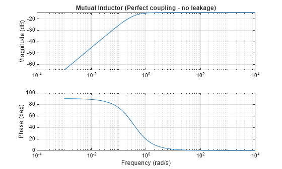
A Comparison of the Mutual Inductor and Ideal Transformer Library Blocks
The differences in behavior between the Mutual Inductor and Ideal Transformer blocks in the Simscape™ Foundation Library. These two blocks both represent the same system of electromagnetically-coupled windings but make different simplifying assumptions. It is important to understand the assumptions and how they impact model fidelity as a function of frequency. With this, you can make an informed decision about which block to use in a model of your circuit.
Ports
Conserving
Parameters
Extended Capabilities
Version History
Introduced in R2007a