Event-Driven Tasks
Event-driven tasks start executing when triggered by an external event. Events can include internal events, such as memory stream or register writes, or external events, such as receiving a UDP data packet from a network connection. Assuming no other tasks are executing at the time of the event or the task has the highest priority, the event-driven task can respond immediately to the event. The task can then process the received data, and potentially generate other events in the model.
Note
The triggered-subsystem of an event driven task can contain one and only one block that can generate new events.
Create a Simulink Model with an Event Driven Task
This example shows how to create and configure a Simulink® model to use the event driven task feature of the SoC Blockset.
Create a Software Reference Model
This section shows how to create a reference model of the software for an SoC application model. The software contains an event driven task subsystem that reacts to receiving UDP packets.
Create a new blank model.
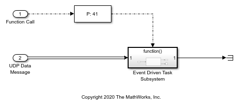
In the Simulink editor, add a Function-Call Subsystem block to the model. Connect an Inport block to the input port of the Function-Call Subsystem block. Connect the output port to a Terminator block.
Add an Asynchronous Task Specification block to the model. On the Block Parameters dialog box, set the Task priority to
41.Connect the output port of Asynchronous Task Specification block to the function() input of the Function-Call Subsystem block.
Add an Inport block and open the Block parameters dialog box. On the Signal Attributes tab, check Output function call. Connect the Inport block to the input port of the Asynchronous Task Specification block.
Open the Function-Call subsystem model.
Add a UDP Read block to model. Open the Block Parameters dialog box, set Maximum data length (elements) to
1024and check Enable event-based execution.Connect the Inport block to the UDP Read block UDP Data port. Connect the Data port to the Outport block. Connect the Length port to a Terminator block.
Open the Configuration Parameters dialog box, select the Solver pane. Set Solver selection > Type to
Fixed-stepand check Tasking and sample timer options > Higher priority value indicates higher task priority.Select the Hardware Implementation pane, set Hardware board to
Zedboard.Save the model as
soc_task_createeventdriventask_software.slx.
The completed model should look similar to the following model.

Create the SoC Application Model
This section shows how to create the top level SoC application model that contains the software reference model developed in the previous section.
Create a new blank model.
In the Simulink editor, add a Model block. On the Block Parameters dialog box, set Model name to
soc_task_createeventdriventask_software.slx.Add a Task Manager block and open the Block Parameters dialog box. Set the Main > Type to
Event-drivenand Main > Priority to41. Each newly added event-driven task exposes an event message input port on the Task Manager block.(Optional) On the Simulation tab, you specify the task duration for that task. For more information on setting task duration, see Task Duration.
In the editor, add an IO Data Source block to the model. Open the Block Parameters dialog box and set the Show port parameter to
Data and Event.Connect the IO Data Source block Event port to the Task Manager and the UDP Data port to the UDP Data Message port on the Model reference block.
Open the Configuration Parameters dialog box, select the Solver pane. Set Solver selection > Type to
Fixed-stepand check Tasking and sample timer options > Higher priority value indicates higher task priority.Select the Hardware Implementation pane, set Hardware board to
Zedboard.Update the diagram, press Ctrl+D.
Save the model as
soc_task_createeventdriventask_application.slx.
The completed model should look similar to the following model.

Run the Model with Event Driven Task
In the Simulink editor, run the soc_task_createeventdriventask_application.slx model. When the run completes, open the Simulation Data Inspector and select Task1. The Simulation Data Inspector shows that Task1 triggers and executes each time a new UDP packet arrives. Although superficially the task execution appears periodic, this is only a byproduct of the current default settings of the IO Data Source block that generates the event with a time step of 0.1.
