EtherCAT Protocol Detect Network Failure and Reset
This example shows how to use the EtherCAT® Notifications block to detect a failure in the connected network and to restart the network when the failure is corrected.
Only a disconnected Ethernet cable into the first subordinate device is detected by this example. More complicated failure situations can be detected if you study the pattern of notifications that result and write the embedded MATLAB® block to account for those.
Requirements
To run this example as presented, you need a Beckhoff® EK1100 with EL1202, EL2202-0100, EL3102 and EL4032 subordinate device modules. The model does not write to any process objects. Replacing the ENI file with one appropriate to your network works as well.
EtherCAT in Simulink® Real-Time™ requires a dedicated network port on the target computer that is reserved for EtherCAT use by using the Ethernet configuration tool. Configure the dedicated port for EtherCAT communication, not with an IP address. The dedicated port must be distinct from the port used for the Ethernet link between the development and target computers.
To test this model:
Connect the port that is reserved for EtherCAT in the target computer to the EtherCAT IN port of the EK1100 interface module.
Make sure the EK1100 is supplied with a 24-volt power source.
Build and download the model onto the target.
For a complete example that configures the EtherCAT network, configures the EtherCAT main node model, and builds then runs the real-time application, see Modeling EtherCAT Networks.
Open the Model
This model is a beginning of a full implementation to catch network failures and reinitialize the network once the failure is fixed. The simple state machine in the embedded MATLAB block can be replaced with a State Flow implementation, which may be necessary for more complicated failure detection and recovery.
The EtherCAT initialization block requires that the configuration ENI file is present in the current folder or on the MATLAB path because the file name is present without directory information.
If you want to modify this model to experiment with it, copy the example configuration file and the model file from the example folder to the current folder. To open the model, in the MATLAB Command Window, type:
model = 'slrt_ex_ethercat_notifyreset';
open_system(model);
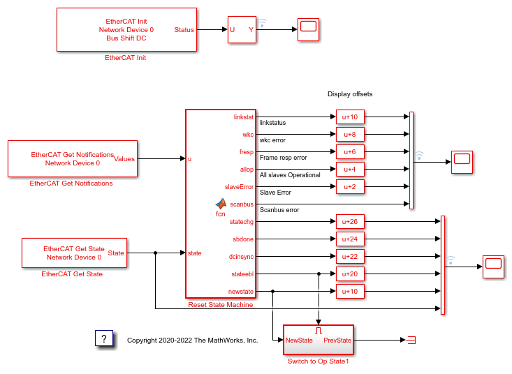
Figure 1: EtherCAT model for detecting a disconnected Ethernet cable at the first subordinate device and reinitializing the network once the cable is reconnected.
Configure the Model
Open the parameter dialog for the EtherCAT Init block and observe the pre-configured values. The EtherCAT subordinate devices that are daisy chained together with Ethernet cable is a Device, also referred to as an EtherCAT network. The Device Index selects one such chained EtherCAT network. The Ethernet Port Number identifies which Ethernet port to use to access that Device. The EtherCAT Init block connects these two so that other EtherCAT blocks use the Device Index to communicate with the subordinate devices on that EtherCAT network.
If you only have one connected network of EtherCAT subordinate devices, and you have only reserved one Ethernet port with the Ethernet configuration tool, use Device Index = 0 and Ethernet Port Number = 1.
Create an ENI File for a Different Subordinate Device Network
If you need to create a new ENI file you need to use a third-party EtherCAT configurator such as TwinCAT 3 from Beckhoff that you install on a development computer. The EtherCAT configuration (ENI) file preconfigured for this model is Stack4_BS_1ms.xml.
Each ENI file is specific to the exact network setup for which it was created (for example, the network discovered in step 1 of the configuration file creation process). The configuration file provided for this example is valid if and only if the EtherCAT network consists of a Beckhoff EK1100 with EL1202, EL2202-0100, EL3102 and EL4032 subordinate device modules. If you have a different EtherCAT drive, this example still works, but you need to create a new ENI file that uses your subordinate devices.
For an overview of the process for creating an ENI file, see Configure EtherCAT Network by Using TwinCAT 3.
Build, Download, and Run the Model
To build, download, and run the model:
In the Simulink Editor, from the targets list on the Real-Time tab, select the target computer on which to run the real-time application.
Click Run on Target.
If you open the two scopes by double clicking each, the data is relayed from the target back to the development computer and displayed there.
The model is preconfigured to run for 15 seconds. If you want to run the model longer, pull down the Run on Target menu and change the number on the bottom line. Press the green arrow to configure, build, and run.
Display the Target Computer Data
If you run the model using the Run on Target button, the external mode is connected and you can double click the scope blocks and see the data on the development computer. The Display blocks also work.
When running this model, to demonstrate the reinitialization stages, you need to disconnect and reconnect the Ethernet cable between the target machine and the EtherCAT subordinate device network. When you reconnect the cable, you see the DC timing perform the same resynchronization that occurs during the initial period.
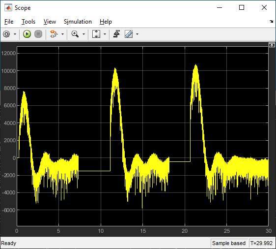
When using Run on Target, Scope shows the DC timing error between the main device code on the target and the first DC enabled subordinate device. Because the error is returned as nanoseconds, this graph shows that the timing difference settles down to the order of 3-5 microseconds (3000 to 5000 nanoseconds) difference between the DC enabled subordinate devices and the target machine running the code. The residual scatter just reflects task scheduling variability in the target computer RTOS.
In this experimental run, the Ethernet cable was disconnected twice during the 30 second run. Disconnection occurred at about 7 seconds, reconnection at about 12 seconds. This process repeats at about 18 seconds and 21 seconds. Each time the cable is reconnected, the timing error shows a pulse that shows drift between target and EtherCAT network during the time the cable was disconnected and is the expected resynchronization behavior.
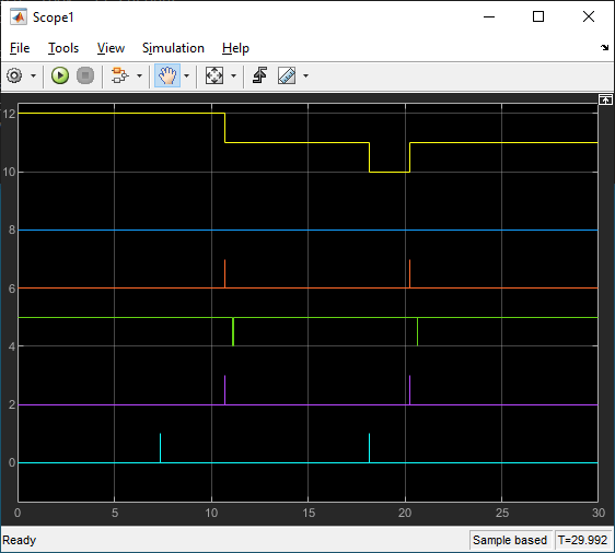
Scope1 shows several logical signals with vertical offsets to show a logic analyzer like display. From the top of the image these are:
Link status (yellow)
Working count error (blue)
Frame response error (red)
All subordinate devices Operational (green)
Subordinate Device Error (purple)
Scanbus error (light blue)
Disconnecting the cable caused a scanbus error as seen on the light blue trace. Nothing happens until the cable is reconnected at about 12 seconds. The link status reflects the single time step notifications that indicate the link going away and the link coming back. On the first disconnection, you do not see the link going away notification, but you do see the link coming back. The embedded MATLAB block keeps a persistent variable with the link status with an initial value of 2 and changes it depending on the notifications.
After the link comes back, there is both a subordinate device error and frame response error before All Subordinate Devices Operational goes down for a sample time. At that point timing resynchronization starts and you see the damped wave showing the timing errot falling to within a few microseconds of error.

Scope2 shows more status outputs with:
statechange (yellow)
sbdone (blue)
dcinsync (red)
statechange request (green)
newstate (purple)
current state (light blue)
When the link goes down, the stack notices that and performs a scan of devices on the bus. That is the sbdone mark at about 7 seconds that also resulted in the sbscan error shown in Scope1. Next when the link is restored at 12 seconds, another bus scan is performed, shown at 12 seconds in the blue trace. The embedded MATLAB block requests a state change to PreOp (=2) shown in the green and purple traces. Once Preop is reached, you see another state change request to go to Op (=8) state which is the second change in green and purple. That starts resynchronization of the clocks between the development comptuer and the target computer, which takes a few seconds until you see dcinsync at about 14 seconds (red trace) with the transition to Op state right after.
Disconnect the cable again to repeat the whole sequence again starting at about 18 seconds.
While this example needs manual intervention to disconnect and reconnect the Ethernet cable, the same restart can be invoked by just requesting PreOp state follwed by a request for Op state, skipping the interaction with the link status if triggered by some other condition in the model.
If you run the model from the command line, you can use the Simulation Data Inspector to view any signal that is marked for signal logging. Signals marked for logging appear with the dot with two arcs above it in the model editor.
See Also
bdclose(model);