Generate Test Cases for Model Decision Coverage
Construct the Example Model
Construct a model for this example:
Create a Simulink® model.
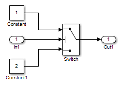
Copy the following blocks into your empty model window:
From the Sources library, an Inport block to initiate the input signal whose value Simulink Design Verifier™ controls.
From the Sources library, two Constant blocks to serve as Switch block data inputs.
From the Signal Routing library, a Switch block to provide simple logic.
From the Sinks library, an Outport block to receive the output signal.
In your model, double-click one of the Constant blocks and specify its Constant value parameter as
2.Connect the blocks so that your model appears similar to the following diagram.
On the Apps tab, click the arrow on the right of the Apps section.
Under Model Verification, Validation, and Test, click Design Verifier.
On the Design Verifier tab, in the Prepare section, from the drop-down menu for the mode settings, click Settings.
In the Configuration Parameters dialog box, select Solver pane. In the Solver selection:
Set the Type option to
Fixed-step.Set the Solver option to
Discrete (no
                                    continuous states)
.
Simulink Design Verifier analyzes only models that use a fixed-step solver.
Click OK to save your changes and close the Configuration Parameters dialog box.
Save your model with the name
ex_generate_test_cases_example.
Check Compatibility of the Example Model
Every time Simulink Design Verifier analyzes a model, before the analysis begins, the software performs a compatibility check. If your model is not compatible, the software cannot analyze it.
Before you start the analysis, you can also make sure that your model is compatible with Simulink Design Verifier software:
Open the
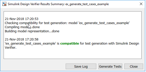
ex_generate_test_cases_examplemodel.On the Design Verifier tab, click Check Compatibility.
The software displays the log window, which states whether or not your model is compatible for analysis.
The model you just created is compatible.
Configure Test Generation Options
Configure Simulink
Design Verifier to generate test cases that achieve 100% decision coverage for the
ex_generate_test_cases_example model:
Open the
ex_generate_test_cases_examplemodel.On the Design Verifier tab, in the Mode section, select Test Generation.
Click Test Generation Settings.
In the Configuration Parameters dialog box, on the Test Generation pane, set the Model coverage objectives parameter to
Decision.For this example, the analysis generates test cases that record only decision coverage.
The Test suite optimization parameter is set by default to
Auto. If you want to generate fewer but longer test cases, selectLongTestcasesfor the Test suite optimization parameter.Click OK to save your changes and close the Configuration Parameters dialog box.
Save the
ex_generate_test_cases_examplemodel.
Analyze the Example Model
On the Design Verifier tab, click Generate Tests. The Simulink Design Verifier analyzes your model to generate test cases.
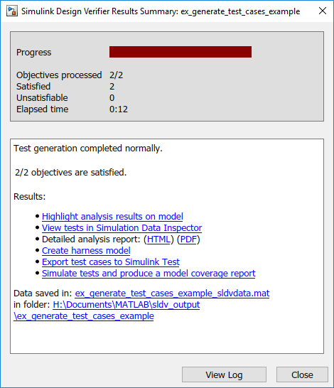
During the analysis, the Results Summary window shows the progress of the analysis. It displays information such as the number of test objectives processed and which objectives are satisfied.
Review Analysis Results
When the software completes its analysis, the Results Summary window displays these options for reviewing the results.
The following sections describe how you can review the analysis results:
Review Analysis Results on the Model
Highlight the analysis results on the example model:
In the Results Summary window for the
ex_generate_test_cases_exampleanalysis, click Highlight analysis results on model.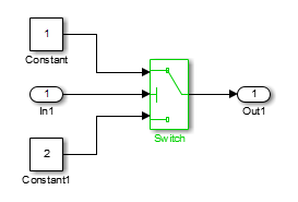
The Switch block is highlighted in green, which indicates that the Switch block has test cases that satisfy its test objectives.
The Simulink Design Verifier Results window opens. As you click objects in the model, this window changes to display detailed analysis results for that object. By default, the Simulink Design Verifier Results window is always the topmost visible window. To allow the window to move behind other window, click
 and clear
Always on
top.
and clear
Always on
top.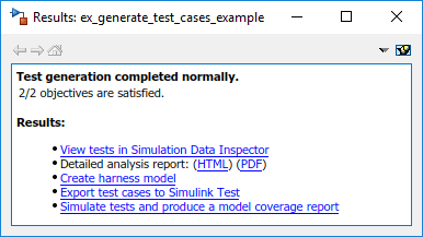
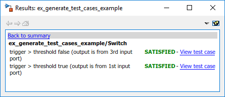
Click the highlighted Switch block.
The Simulink Design Verifier Results window indicates that the analysis generated test cases for both test objectives:
trigger > thresholdtrigger < threshold
For more information about highlighted analysis results on a model, see Highlight Results on the Model.
Review Detailed Analysis Report
Create a detailed HTML analysis report:
In the Simulink Design Verifier Results Summary window, in Detailed analysis report, click HTML.
The HTML report opens in a browser window.
The report includes the following Table of Contents. Click a hyperlink to navigate to a section in the report.

In the Table of Contents, click
Summaryto display the report's Summary chapter.The Summary chapter lists information about the model and the status of the objectives—satisfied or not.
In the Table of Contents, click
Analysis
                                Information
to display the Analysis Information chapter.The Analysis Information chapter provides information about:
The model that you analyzed.
The options that you specified for the analysis.
Approximations the software performed during the analysis.
In the Table of Contents, click
Test
                                Objectives Status
to display the report's Test Objectives Status chapter.This table indicates that the analysis satisfied both test objectives associated with the Switch block in the
ex_generate_test_cases_examplemodel, for which it generated two test cases.Under the table Test Case column, click
2to display the Test Case 2 section.This section provides details about a test case that the analysis generated to achieve an objective in your model. This test case achieves test objective 1, when the Switch block passes its third input to its output port. Specifically, the software determines that a value of –1 for the Switch block control signal causes the block to pass its third input as the block output.
For more information about the HTML reports, see Review Results from Analysis Report.
Review Harness Model
To create a harness model with test cases that satisfy the test objectives in your model, in the Simulink Design Verifier Results Summary window, click Create harness model.
The software creates a harness model named
ex_generate_test_cases_example_harness.
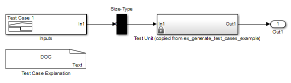
The Signal Editor block named Inputs contains the test cases.
Double-click the Inputs block to see the test case. From the
Signal Editor block, you can simulate the model using the
test cases and produce a model coverage report, as described in Simulate Tests and Produce a Model Coverage Report.
For more information about the harness model, see Use Harness Model for Test Simulations.
If Analysis Generates Many Test Cases. If you have a large model, the analysis might produce a harness model that contains a large number of test cases.
To generate fewer test cases:
Set the Test suite optimization parameter to
LongTestcases.Rerun the analysis.
In the LongTestcases optimization, the analysis
generates fewer but longer test cases that each satisfy multiple test
objectives.
Simulate Tests and Produce a Model Coverage Report
To simulate the harness model using the generated test cases in the harness model:
In the harness model, double-click the
Inputsblock to open the Block Parameters dialog box, then click the Open Signal Editor button to open Signal Editor dialog box.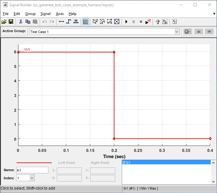
In the model harness window, click Run all.
The software simulates the harness model using both test cases, collects model coverage information, and displays a coverage report. The coverage report indicates that the test cases record 100% decision coverage for the
ex_generate_test_cases_examplemodel.
You can also simulate the model without creating a harness model. In the Simulink Design Verifier log window, click Simulate tests and produce a model coverage report.
For more information about model coverage, see Top-Level Model Coverage Report (Simulink Coverage).
View sldvData File
The Simulink
Design Verifier data file is a MAT file that contains a structure named
sldvData. This structure stores
all the data that the analysis gathers and
produces during the analysis. You can use the data file to conduct your own
analysis or to generate a custom report.
To view the data file, click the data file name in the log window which in
this example is ex_generate_test_cases_example_sldvdata.mat.
When you click the data file name, the software creates a copy of the
sldvData object in the MATLAB® workspace so that you can review and manipulate the data.
For more information about Simulink Design Verifier data files, see View and Understand Analysis Results from Data Files.
Review Analysis Results in the Results Summary Window
As long as your model remains open, you can view the results of your most recent Simulink Design Verifier analysis in the Results Summary window.
On the Design Verifier tab, in the Review Results section, click Load Earlier Results or Results Summary to view the results.
For any Simulink Design Verifier analysis, you can perform these tasks from the Results Summary window.
| Task | For more information |
|---|---|
Highlight the analysis results on the model. | Highlight Results on the Model |
Generate a detailed analysis report. | Review Results from Analysis Report |
Create the harness model, or if the harness model already exists, open it. If no test cases were generated during the analysis, this option is not available. | Use Harness Model for Test Simulations |
View the data file. | View and Understand Analysis Results from Data Files |
View the log file. | Analyze Model and Interpret Results |
After you close your model, you can no longer view analysis results.
Customize Test Generation
You can use the Test Condition block to constrain signals in your model to certain values during the analysis.
At the MATLAB command prompt, enter
sldvlibto display the Simulink Design Verifier library.Open the Objectives and Constraints sublibrary.
Copy the Test Condition block to your model by dragging it from the Simulink Design Verifier library to your model window.
In the model window, insert the Test Condition block between the Inport and Switch blocks.

Double-click the Test Condition block to access its attributes.
The Block Parameters dialog box opens.
In the Values box, enter
[-0.1,
                            0.1]
. When generating test cases for this model, the analysis constrains the signal values, entering the Switch block control port to the specified range.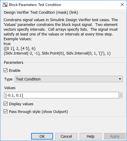
Click OK to save your changes and close the Block Parameters dialog box.
Save your model as
ex_generate_test_cases_with_tc_blockand keep it open.
Reanalyze the Example Model
Analyze the ex_generate_test_cases_with_tc_block model with the
Test Condition block. To observe how the Test
Condition block affects test generation, compare the result of this
analysis to the result that you obtained in Analyze Example Model.
On the Design Verifier tab, click Generate Tests.
The Simulink Design Verifier software displays a log window and begins analyzing your model to generate test cases. When the software completes the analysis, the Results Summary window displays the options for reviewing the results.
In the Results Summary window, click HTML Report.
To begin reviewing the report, in the Table of Contents, click Summary.
The Summary chapter indicates that Simulink Design Verifier satisfied two test objectives in the model.
In the Table of Contents, click Analysis Information. Scroll to the bottom of this chapter, to the Constraints section.
This section lists the Test Condition block that you added to constrain the value of the Switch block control signal to the interval [–0.1, 0.1].
In the Table of Contents, click Test Objectives Status.
This table indicates that Simulink Design Verifier satisfied both test objectives for the Switch block through the two test cases generated.
Under the table Test Case column, click 1.
This section provides details about a test case that the software generated to achieve an objective in your model. This test case achieves test objective 1, when the Switch block passes its third input to its output port. Although the Test Condition block restricts the domain of input signals to the interval [–0.1, 0.1], the software determines that a value of –0.1 for the Switch block control signal satisfies this objective.
To confirm that the test case achieves 100% decision coverage, open the harness model.
Double-click the Inputs block to open the Signal Editor dialog box.
In the toolstrip for the Harness model, click Run all (Coverage).
The Simulink software simulates the harness model using both test cases, collects model coverage information, and displays a coverage report. The Summary section of the report indicates that Simulink Design Verifier generated test cases that achieve complete decision coverage for your example model.
Analyze Contradictory Models
If the analysis produces the error The model is contradictory in its
current configuration, the software detected a contradiction in your
model and cannot analyze the model.
You can have a contradiction if your model has Test Objective blocks with incorrect parameters. For example, a contradiction can be an objective that states that a signal must be between 0 and 5 when the signal is the constant 10.
If the software detects a contradiction, all previous results are invalidated and the software reports that some of the objectives cannot be satisfied.