sim3d.sensors.Camera
Description
Use the sim3d.sensors.Camera object to create a camera with a lens in
the 3D environment. The sensor is based on the ideal pinhole camera model, with a lens added
to represent a full camera model, including lens distortion. This camera object supports a
field of view of up to 150 degrees without distortions. For more details, see Algorithms. After you create a
sim3d.sensors.Camera object, you can modify aspects of the actor object by setting
property values.
Creation
Description
camera = sim3d.sensors.Camera()sim3d.sensors.Camera object in the 3D environment.
camera = sim3d.sensors.Camera(Name=Value)FocalLength to [200
200].
Name-Value Arguments
Specify optional pairs of arguments as
Name1=Value1,...,NameN=ValueN, where Name is
the argument name and Value is the corresponding value.
Name-value arguments must appear after other arguments, but the order of the
pairs does not matter.
Example: camera =
sim3d.sensors.Camera(ActorName=Camera,ImageSize=[768,1024],FocalLength=[1109,1109])
The intrinsic camera parameters are equivalent to the properties of a cameraIntrinsics (Computer Vision Toolbox) object. To obtain the intrinsic parameters for your camera,
use the Camera Calibrator app. An arbitrary combination of intrinsic camera
parameters produces invalid images. The sim3d.sensors.Camera object supports a
field of view of up to 95 degrees with distortions. For a list of the maximum fields of
view for different camera models, see Fisheye Calibration Basics (Computer Vision Toolbox).
For details about the camera calibration process, see Using the Single Camera Calibrator App (Computer Vision Toolbox) and What Is Camera Calibration? (Computer Vision Toolbox).
Name of actor, specified as a character array or string. If you do not specify an actor name,
then the software assigns the actor an autogenerated name. Use
this argument to set the name of the
sim3d.sensors.Camera object.
Note
If you specify the same name as an actor that already exists, then the software appends actor name you specify with a unique identifier.
Since R2025a
Coordinate system that the actor uses for translation and rotation in the 3D environment, specified as one of these listed values:
'Default'– World coordinate system'MATLAB'– MATLAB® coordinate system'ISO8855'– ISO 8855 standard coordinate system'AERO'– SAE coordinate system'VRML'– X3D ISO standard coordinate system'SAE'– SAE coordinate system
For more details on the different coordinate systems, see Coordinate Systems in Simulink 3D Animation.
Data Types: string
Relative translation
(x,y,z) of the actor object to its
parent actor, specified as a real 1-by-3 vector. Use Translation to change
the position of the sim3d.sensors.Camera object in the 3D environment along the
X, Y, and Z axes of the
coordinate system. When you add an actor to the 3D environment, the default parent actor is the
Scene Origin at (0,0,0).
Example: Translation=[1 2 1]
Relative rotation (roll,
pitch, yaw) of the actor object to its parent actor,
specified as a real 1-by-3 vector. When you add an actor to the 3D environment, the default
parent actor is the Scene Origin at (0,0,0). The rotation
order is roll, then pitch, then yaw.
When you update any of the three rotation values and leave others unchanged, the software
reapplies all three rotations in the same order.
Example: Rotation=[pi/4 pi/8 pi/2]
Focal length of camera, specified as a real-valued 1-by-2 vector of positive integers of the form [fx, fy], in pixels.
fx = F × sx
fy = F × sy
where:
F is the focal length in world units, typically millimeters.
[sx, sy] are the number of pixels per world unit in the x and y direction, respectively.
FocalLength is equivalent to the FocalLength (Computer Vision Toolbox) property
of a cameraIntrinsics object.
Optical center of camera, specified as a real-valued 1-by-2
vector of positive integers of the form [cx,cy], in
pixels. OpticalCenter is equivalent to the PrincipalPoint (Computer Vision Toolbox)
property of a cameraIntrinsics object.
Image size produced by the sim3d.sensors.Camera
object, specified as a real-valued 1-by-2 vector of positive integers of the form
[m,n], in pixels. m is the vertical
resolution and n is the horizontal resolution. ImageSize
is equivalent to the ImageSize (Computer Vision Toolbox) property of a
cameraIntrinsics object.
Radial distortion coefficients, specified as a real-valued 2-element, 3-element, or 6-element vector. Radial distortion is the displacement of image points along radial lines extending from the principal point.
As the image points move away from the principal point (positive radial displacement), image magnification decreases, and a pincushion-shaped distortion occurs on the image.
As the image points move toward the principal point (negative radial displacement), image magnification increases, and a barrel-shaped distortion occurs on the image.
The camera sensor calculates the (xd,yd) radial-distorted location of a point using a two-coefficient, three-coefficient, or six-coefficient formula. This table shows the formulas, where:
(x,y) = undistorted pixel locations
k1,k2,k3,k4,k5,k6 = radial distortion coefficients of the lens
r2 = x2 + y2
| Coefficients | Formula | Description |
[k1, k2] |
xd = x(1 + k1r2 + k2r4) yd = y(1 + k1r2 + k2r4) | This model is equivalent to the two-coefficient model used by the
RadialDistortion (Computer Vision Toolbox) property of a
cameraIntrinsics object. |
[k1, k2, k3] |
xd = x(1 + k1r2 + k2r4 + k3r6) yd = y(1 + k1r2 + k2r4 + k3r6) | This model is equivalent to the three-coefficient model used by the
RadialDistortion (Computer Vision Toolbox) property of a
cameraIntrinsics object. |
[k1, k2, k3, k4, k5, k6] | The six-coefficient model is based on the OpenCV radial distortion model. Note The Camera Calibrator app does not support this model. To calibrate a camera using this model, see Camera Calibration and 3D Reconstruction in the OpenCV documentation. |
Tangential distortion coefficients, specified as a real-valued 2-element vector. Tangential distortion occurs when the lens and the image plane are not parallel.
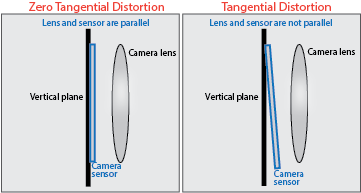
The camera sensor calculates the tangential distorted location of a point, (xd, yd), using this formula:
xd = x + [2p1xy + p2 × (r2 + 2x2)]
yd = y + [p1 × (r2 + 2y2) + 2p2xy]
where:
x, y = undistorted pixel locations
p1, p2 = tangential distortion coefficients of the lens
r2 = x2 + y2
The undistorted pixel locations appear in normalized image coordinates, with the origin at the optical center. The coordinates are expressed in world units. TangentialDistortionCoefficients is equivalent to the TangentialDistortion (Computer Vision Toolbox) property of a cameraIntrinsics object.
Skew angle of camera axes, specified as a nonnegative real-valued scalar. If the X-axis and Y-axis are exactly perpendicular, then the skew must be 0. Units are dimensionless. Skew is equivalent to the Skew (Computer Vision Toolbox) property of a cameraIntrinsics object.
Option to enable depth output, specified as 0
(false) if depth output is not enabled or 1
(true) if it is enabled.
Example: EnableDepthOutput=1
Option to enable semantic output, specified as 0
(false) if semantic output is not enabled or
1 (true) if it is enabled.
Example: EnableSemanticOutput=1
Since R2025a
Option to visualize the camera field of view, specified as 0
(false) if the visualization is not enabled or
1 (true) if it is enabled. This argument
enables visualization of the field of view with a segmented sphere to annotate the
boundaries and extent of the field of view.
Example: VisualizeFieldOfView=1
Data Types: logical
Since R2025a
Visualization range of camera coverage, specified in meters. Use this argument to set the radius of the segmented sphere.
Example: FieldOfViewRange=41
Dependencies
To enable this argument, set VisualizeFieldOfView to
1.
Data Types: double
Output Arguments
Properties
Parent of actor, specified as a handle to the parent actor
object. After you add an actor to the sim3d.World object, the default parent
actor is the Scene Origin at (0,0,0). Use
Parent to set any actor in the 3D environment as the parent actor of a
sim3d.sensors.Camera object.
This property is read-only.
Children of actor, specified as a structure.
Each field of the structure contains a handle to
the child of a sim3d.sensors.Camera
object.
Parent world, specified as a handle to the parent sim3d.World
object. You can use this property only if the sim3d.sensors.Camera object is
added to the parent sim3d.World object.
This property is read-only.
Unique ID of the sensor, specified as a real positive scalar.
Data Types: uint32
Since R2025a
Coordinate system that the actor uses for translation and rotation in the 3D environment, specified as one of these listed values:
'Default'– World coordinate system'MATLAB'– MATLAB coordinate system'ISO8855'– ISO 8855 standard coordinate system'AERO'– SAE coordinate system'VRML'– X3D ISO standard coordinate system'SAE'– SAE coordinate system
For more details on the different coordinate systems, see Coordinate Systems in Simulink 3D Animation.
Data Types: string
Relative translation
(x,y,z) of the actor object to its
parent actor, specified as a real 1-by-3 vector. Use Translation to change
the position of the sim3d.sensors.Camera object in the 3D environment along the
X, Y, and Z axes of the
coordinate system. When you add an actor to the 3D environment, the default parent actor is the
Scene Origin at (0,0,0).
Example: camera.Translation = [1 2 1]
Relative rotation (roll,
pitch, yaw) of the actor object to its parent actor,
specified as a real 1-by-3 vector. When you add an actor to the 3D environment, the default
parent actor is the Scene Origin at (0,0,0). The rotation
order is roll, then pitch, then yaw.
When you update any of the three rotation values and leave others unchanged, the software
reapplies all three rotations in the same order.
Example: camera.Rotation = [pi/4 pi/8 pi/2]
Type of actor mobility to respond to physics, move the actor during simulation, or both, specified as one of these options.
'Static'– Actors do not move or update during simulation, and the software uses precomputed lighting.'Stationary'– Actors do not move or update during simulation, and the software uses dynamic lighting such as casting shadows.'Movable'– Actors can move or update during simulation, and the software uses dynamic lighting.
Example: camera.Mobility = 'Movable'
Focal length of camera, specified as a real-valued 1-by-2 vector of positive integers of the form [fx, fy], in pixels.
fx = F × sx
fy = F × sy
where:
F is the focal length in world units, typically millimeters.
[sx, sy] are the number of pixels per world unit in the x and y direction, respectively.
FocalLength is equivalent to the FocalLength (Computer Vision Toolbox) property
of a cameraIntrinsics object.
Optical center of camera, specified as a real-valued 1-by-2
vector of positive integers of the form [cx,cy], in
pixels. OpticalCenter is equivalent to the PrincipalPoint (Computer Vision Toolbox)
property of a cameraIntrinsics object.
Image size produced by the sim3d.sensors.Camera
object, specified as a real-valued 1-by-2 vector of positive integers of the form
[m,n], in pixels. m is the vertical
resolution and n is the horizontal resolution. ImageSize
is equivalent to the ImageSize (Computer Vision Toolbox) property of a
cameraIntrinsics object.
Radial distortion coefficients, specified as a real-valued 2-element, 3-element, or 6-element vector. Radial distortion is the displacement of image points along radial lines extending from the principal point.
As the image points move away from the principal point (positive radial displacement), image magnification decreases, and a pincushion-shaped distortion occurs on the image.
As the image points move toward the principal point (negative radial displacement), image magnification increases, and a barrel-shaped distortion occurs on the image.
The camera sensor calculates the (xd,yd) radial-distorted location of a point using a two-coefficient, three-coefficient, or six-coefficient formula. This table shows the formulas, where:
(x,y) = undistorted pixel locations
k1,k2,k3,k4,k5,k6 = radial distortion coefficients of the lens
r2 = x2 + y2
| Coefficients | Formula | Description |
[k1, k2] |
xd = x(1 + k1r2 + k2r4) yd = y(1 + k1r2 + k2r4) | This model is equivalent to the two-coefficient model used by the
RadialDistortion (Computer Vision Toolbox) property of a
cameraIntrinsics object. |
[k1, k2, k3] |
xd = x(1 + k1r2 + k2r4 + k3r6) yd = y(1 + k1r2 + k2r4 + k3r6) | This model is equivalent to the three-coefficient model used by the
RadialDistortion (Computer Vision Toolbox) property of a
cameraIntrinsics object. |
[k1, k2, k3, k4, k5, k6] | The six-coefficient model is based on the OpenCV radial distortion model. Note The Camera Calibrator app does not support this model. To calibrate a camera using this model, see Camera Calibration and 3D Reconstruction in the OpenCV documentation. |
Tangential distortion coefficients, specified as a real-valued 2-element vector. Tangential distortion occurs when the lens and the image plane are not parallel.
The camera sensor calculates the tangential distorted location of a point, (xd, yd), using this formula:
xd = x + [2p1xy + p2 × (r2 + 2x2)]
yd = y + [p1 × (r2 + 2y2) + 2p2xy]
where:
x, y = undistorted pixel locations
p1, p2 = tangential distortion coefficients of the lens
r2 = x2 + y2
The undistorted pixel locations appear in normalized image coordinates, with the origin at the optical center. The coordinates are expressed in world units. TangentialDistortionCoefficients is equivalent to the TangentialDistortion (Computer Vision Toolbox) property of a cameraIntrinsics object.
Skew angle of camera axes, specified as a nonnegative real-valued scalar. If the X-axis and Y-axis are exactly perpendicular, then the skew must be 0. Units are dimensionless. Skew is equivalent to the Skew (Computer Vision Toolbox) property of a cameraIntrinsics object.
Object Functions
read | Return image data captured with camera |
Examples
Since R2025a
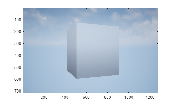
Create a camera in the 3D environment using the sim3d.sensors.Camera object. You can capture images of the 3D environment and display them in MATLAB®. Use the read function to extract image data from the 3D environment.
Create a 3D environment and set up communication with the Unreal Engine simulation environment using the output function OutputImpl and the update function UpdateImpl. The sim3d.World object can send and receive data about the 3D environment to and from the Unreal Engine at each simulation step using output and update functions, respectively. Before the Unreal Engine simulates, MATLAB calls the output function and sends data to the Unreal Engine. Then, the Unreal Engine executes at each time step and sends data to MATLAB in the update function. You can use the update function to read this data or change values after each simulation step.
world = sim3d.World(Output=@outputImpl,Update=@updateImpl);
Create a box actor in the 3D environment using the sim3d.Actor object and add the box to the world.
cube = sim3d.Actor( ...
        ActorName="Cube", ...
        Mobility='Movable');
createShape(cube,"box");
add(world,cube);
Create a camera object using the sim3d.sensors.Camera object and set the location of the camera using the Translation property. Add the camera to the world.
camera = sim3d.sensors.Camera( ...
        ActorName="Camera");
camera.Translation = [-3 0 0];
add(world,camera);
Run the co-simulation.
sampletime = 1/60;
stoptime = 2;
run(world,sampletime,stoptime);
Output Function
The output function sends data about the actor to the Unreal Engine environment at each simulation step. For this example, the function rotates the Cube about its Z-axis by updating the Rotation property of the Cube at each simulation step.
function outputImpl(world)
    world.Actors.Cube.Rotation(3) = world.Actors.Cube.Rotation(3) ...
    + 0.01;
end
Update Function
The update function reads data from the Unreal Engine environment at each simulation step. For this example, the update function uses the read function of the sim3d.sensors.Camera object to get image data from the Camera in the Unreal Engine environment and uses the image function to display it in MATLAB.
function updateImpl(world)
    sceneImage = read(world.Actors.Camera);
    image(sceneImage);
end
Since R2025a
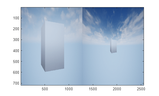
You can examine difference in the image data captured using two cameras with different focal length. Create two cameras in the 3D environment using the sim3d.sensors.Camera object and adjust the focal length of one camera. You can capture images of the 3D environment with both cameras and display them in MATLAB®. Use the read function to extract the image data from the 3D environment.
Create a 3D environment using the sim3d.World object. Set up communication with the Unreal Engine simulation environment using the output function OutputImpl and the update function UpdateImpl.
world = sim3d.World(Output=@outputImpl,Update=@updateImpl);
Create a box actor in the 3D environment using the sim3d.Actor object and add the box to the world.
cube = sim3d.Actor( ...
        ActorName="Cube", ...
        Mobility=sim3d.utils.MobilityTypes.Movable);
createShape(cube,"box");
add(world,cube);
Create a camera object using the sim3d.sensors.Camera object and set the location of the camera using the Translation property. Add the camera1 to the world.
camera1 = sim3d.sensors.Camera( ...
        ActorName="Camera1");
camera1.Translation = [-3 0 0];
add(world,camera1);
Create another camera object using the sim3d.sensors.Camera object and set the location and focal length of the camera using the properties Translation and FocalLength, respectively. Add the camera2 to the world.
camera2 = sim3d.sensors.Camera( ...
        ActorName="Camera2",FocalLength=[300 300]);
camera2.Translation = [-3 0 0];
add(world,camera2);
Run the co-simulation.
sampletime = 1/60;
stoptime = 2;
run(world,sampletime,stoptime);
Output Function
The output function sends data about the actor to the Unreal Engine environment at each simulation step. For this example, the function rotates the Cube about its Z-axis by updating the Rotation property of the Cube at each simulation step.
function outputImpl(world)
    world.Actors.Cube.Rotation(3) = world.Actors.Cube.Rotation(3) ...
        + 0.01;
end
Update Function
The update function reads data from the Unreal Engine environment at each simulation step. For this example, the update function uses the read function of the sim3d.sensors.Camera object to get image data from the Camera1 and Camera2 in the Unreal Engine environment. Use the image function to display the image in MATLAB.
function updateImpl(world)
    sceneImage = [read(world.Actors.Camera1) ...
        read(world.Actors.Camera2)];
    image(sceneImage);
end
Algorithms
References
[1] Bouguet, Jean-Yves. Camera Calibration Toolbox for Matlab. CaltechDATA, 2022. https://doi.org/10.22002/D1.20164.
[2] Zhang, Zhengyou. "A Flexible New Technique for Camera Calibration." IEEE Transactions on Pattern Analysis and Machine Intelligence. 22, no. 11 (2000): 1330–34.
[3] Heikkilä, Janne, and Olli Silven. “A Four-Step Camera Calibration Procedure with Implicit Image Correction.” In Proceedings of IEEE International Conference on Computer Vision and Pattern Recognition. San Juan, PR, June 17–19, 1997: 1106–12. https://doi.org/10.1109/CVPR.1997.609468.
Version History
Introduced in R2024bSee Also
Simulation 3D Camera | sim3d.World | sim3d.Actor | add | run