Getting Started with Dashboard Panels
A dashboard panel floats above the model canvas and follows you through the model hierarchy. Use panels to monitor signals, tune parameters, and debug from anywhere in your model without adding collections of dashboard blocks throughout the model.
You can use panels to model real dashboards, for example, the dashboard in your car. To model displays and controls on the panel, such as gauges, lamps, knobs, buttons, and switches, you can promote blocks to the panel from the Dashboard library, the Customizable Blocks library, and the Aerospace Blockset™ Flight Instruments library.
Note
To use panels saved in a referenced model, open the referenced model as a top model.
By default, the first panel you create in a model has a single tab. To model multiple dashboards, you can make multiple panels or add tabs to a panel. For more information, see Create Tabbed Dashboard Panels.
When you want more of the canvas to be visible so that you can inspect or edit the model in the canvas, you can collapse or hide a panel.
This example shows you how to create, edit, and manage the visibility of a panel for testing a fuel control system.
Open Example Model
Open the sldemo_fuelsys model from the Model Fault-Tolerant Fuel Control System
example.
openExample('simulink_automotive/ModelingAFaultTolerantFuelControlSystemExample')The sldemo_fuelsys model has a Dashboard subsystem
that contains controls and indicators for interactively simulating the model. Navigate
inside the Dashboard subsystem.
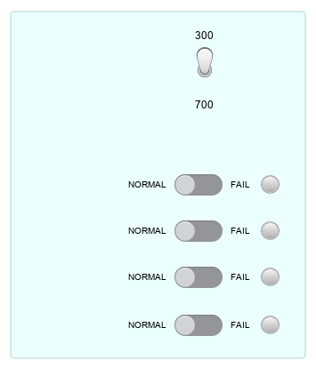
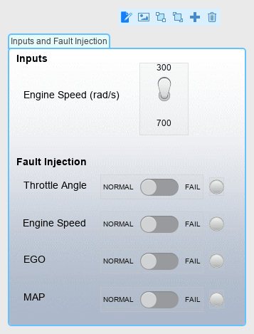
The subsystem contains four areas: Inputs, Fault
Injection, Fuel (g/s), and Air/Fuel
Ratio.
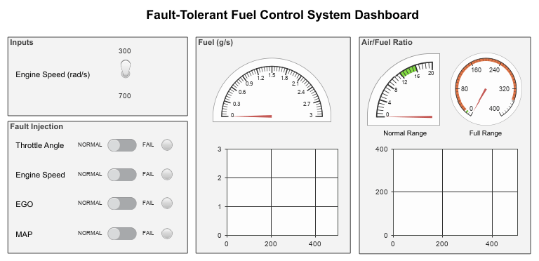
In this example, you create a panel that contains the control blocks from the
Input and Fault Injection areas.
For an example of how you can use such a panel, see Use Dashboard Panels to Monitor Signals and Control Parameters.
Create Panels
To create a new panel, do one of these:
Directly promote a group of selected blocks to a new panel. Use this approach to create your first panel in a model.
Create an empty panel. The option for creating empty panels becomes available after you create your first panel.
Warning
Promoting a block to a panel clears all callback functions of the block except for the
ClickFcnfunction and thePressFcnfunction.Programmatically interacting with a block in a panel is not supported. For example, the
find_system,get_param,set_param,gcb, andgcbhfunctions do not recognize the existence of blocks in panels.
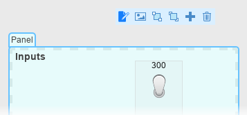
For example, create the first panel in the Dashboard subsystem by
promoting the dashboard block in the Inputs area to a new panel:
Select the block.
Pause on the ellipsis (…) that appears above the block.
In the action bar that appears, click Promote to Panel
 .
.
The Toggle Switch block promotes to the panel, but the annotation
Engine Speed (rad/s) does not.
You can promote blocks to a panel only from the Dashboard library, the Customizable blocks library, and the Aerospace Blockset Flight Instruments library. When you try to promote a selection containing dashboard blocks and other blocks, only the dashboard blocks promote to the panel.
When you use panels, the blocks in the panel are not associated with the model in the
same way as blocks in the canvas. You cannot programmatically interact with blocks in panels
using get_param, set_param, gcb, or
gcbh. Otherwise, blocks promoted to panels retain their interactive
behavior. You can connect dashboard blocks in a panel using connect mode, inspect block
properties using the Property Inspector, and modify connections during simulation. For more
information about connect mode, see Connect Blocks Without Signal Lines.
When you add your first panel to the model, in the Simulink® Toolstrip, the Panels tab appears.
The Panels tab stays visible unless you save and close the model when it does not contain any panels. If you save and close a model without panels, when you reopen the model, the Panels tab is no longer visible. To restore the tab, promote one or more dashboard blocks to a panel.
Now that a panel exists in this model, you can create an empty panel. On the Panels tab, in the Create section, click Add Empty Panel. An empty panel appears.
To delete the panel, select it and press Delete.
Populate and Edit Panels
When the simulation is not running, you can edit panels and the blocks they contain. To make any of these changes, enter edit mode:
Add blocks to the panel using the quick insert menu.
Move blocks from the panel to the canvas.
Move blocks from one panel to another panel.
Move blocks and annotations within a panel.
Resize blocks in a panel.
Annotate a panel.
To enter edit mode:
Click the panel.
Pause on the ellipsis (…) that appears.
In the action bar that expands, click Edit Panel
 .
.
To exit edit mode, click the canvas.
Add Blocks to Panel Using Quick Insert Menu
You can add blocks to an existing panel using the quick insert menu. For example, add a Rocker Switch block from the Customizable blocks library to the panel you created in Create Panels.
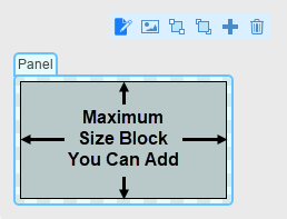
Adding blocks that are bigger than the panel is not supported. Before you add a block to a panel, consider the size of the panel. If needed, resize the panel by dragging the panel corners outward.
Then, specify which block you want to add using one of these methods:
Enter edit mode. In the Simulink Toolstrip, on the Panels tab, click Edit Panels.
Double-click where you want to add the block. You must click a blank space on the panel. The quick insert menu appears where you click. Once the menu appears, type the name of the block.
Use your arrow keys to navigate to the block you want to add in the list of search results, and then press Enter. Alternatively, double-click the block you want to add in the list of search results. The new block appears in the panel.
Enter edit mode. In the Simulink Toolstrip, on the Panels tab, click Edit Panels.
Click where you want to add the block, and then type the name of the block. You must click a blank space on the panel. When you start typing, the quick insert menu appears.
Use your arrow keys to navigate to the block you want to add in the list of search results, and then press Enter. Alternatively, double-click the block you want to add in the list of search results. The new block appears in the panel.
Select the panel and press Ctrl+Period(.) twice, once to open the quick action search menu, and once to switch to the quick insert menu. Type the name of the block.
Use your arrow keys to navigate to the block you want to add in the list of search results, and then press Enter. Alternatively, double-click the block you want to add in the list of search results. The panel enters edit mode, and the new block appears in the panel.
Promote Block to Existing Panel
You can promote blocks to an existing panel.
Warning
Promoting a block to a panel clears all callback functions of the block except for the
ClickFcnfunction and thePressFcnfunction.Programmatically interacting with a block in a panel is not supported. For example, the
find_system,get_param,set_param,gcb, andgcbhfunctions do not recognize the existence of blocks in panels.
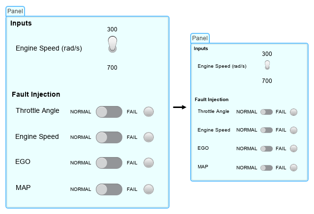
For example, promote the blocks from the Fault Injection area to
the panel you created in Create Panels:
Enter edit mode.
Drag the borders of the panel outwards until all the blocks in the
Fault Injectionarea fit inside the panel borders.Drag the panel away from the
Fault
                Injection
area so that the panel and area no longer overlap. To drag the panel, click and hold down your pointer on the panel name or on any empty spot inside the panel, then move the pointer.Drag the blocks in the
Fault Injectionarea into the panel.To exit edit mode, click the canvas.
Move Block from Panel to Canvas
To move a block to the canvas, enter edit mode and drag the block from the panel to the canvas.
For example, move one of the blocks from the panel you created in Promote Block to Existing Panel to the canvas. To promote the block to the panel again, in edit mode, drag the block back onto the panel. To exit edit mode, click the canvas.
Move Block from One Panel to Another Panel
To move a block from one panel to another panel, enter edit mode, then drag the block to the other panel.
For example, move blocks from the panel you created in Promote Block to Existing Panel into a new panel:
To create a blank panel, in the Simulink Toolstrip, on the Panels tab, in the Create section, click Add Empty Panel.
Enter edit mode.
Resize the panel to be as large as the panel you created in Promote Block to Existing Panel.
Move blocks from the panel you created in Promote Block to Existing Panel to the new panel by dragging them from one to the other.
Move the blocks back.
To exit design mode, click the canvas.
Annotate Panels
You can add text annotations to a panel.
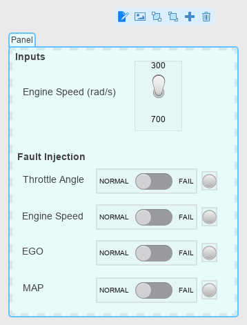
For example, consider the annotations in the Dashboards subsystem,
in the Inputs and Fault Injection areas. Replicate
these annotations in the panel you created in Promote Block to Existing Panel:
Enter edit mode.
To add an annotation, double-click the panel where you want to add the annotation. You can still move the annotation later, so the position at which you double-click does not need to be perfect. For this example, double-click in the upper left of the panel.
In the quick insert menu that appears, the Create Annotation option is selected. Press Enter.
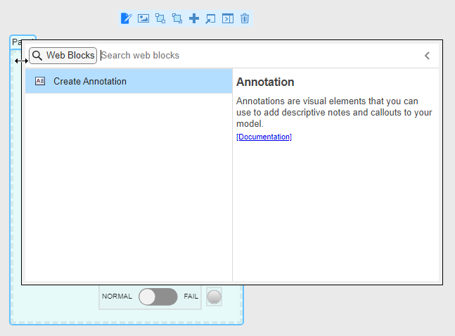
Enter the word
Inputs.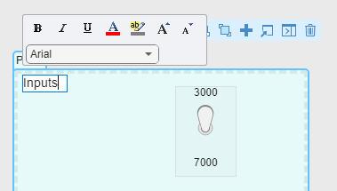
Select the text. In the formatting menu above the text, click Bold.
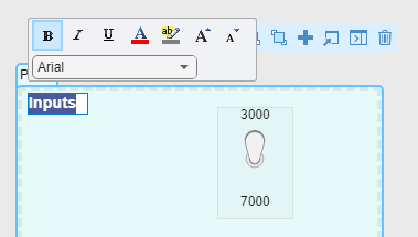
Press Enter.
Add a second bold annotation with the text
Fault Injection. Position it at the left edge of the panel, above the blocks from theFault Injectionarea.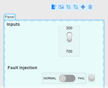
Add the annotations for the dashboard blocks.
To exist edit mode, click the canvas.
To edit an annotation after you create it, double-click the annotation.
To delete an annotation, double-click the annotation and delete all of the text in it.
To move an annotation to a different panel, in edit mode, drag the annotation onto the other panel.
Resize Panels
To promote a block to a panel, the block must fit inside the dashed line that appears along the inside of the panel perimeter when you enter edit mode. If your panel is too small to fit the block you want to promote, resize the panel.
To resize a panel and its contents together, such that the contents scale proportionally to the panel:
If you are in edit mode, click the canvas to exit edit mode.
Drag one of the corners of the panel.
When you are not in edit mode and you resize the panel, the panel maintains its aspect ratio. As you resize the panel, the blocks in the panel scale proportionally.
For example, resize the panel you created in Promote Block to Existing Panel with its contents.
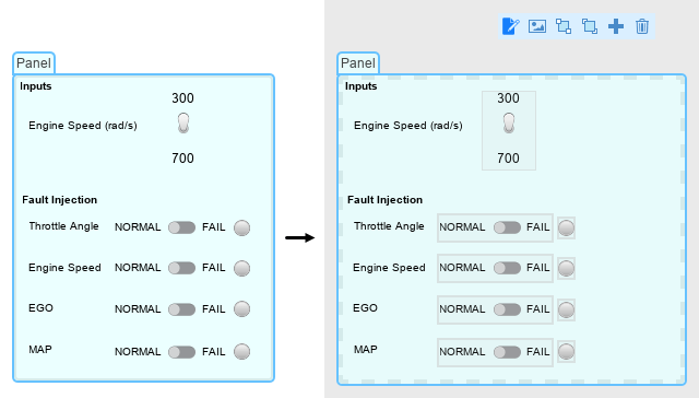
To resize a panel without resizing its contents:
Enter edit mode.
Click and drag one of the corners of the panel.
When you are in edit mode and you resize the panel, the panel does not maintain its aspect ratio. You cannot drag a corner further inwards when doing so would cut off a block or an annotation.
For example, resize the panel you created in Promote Block to Existing Panel without its contents.
Rename Panels
The Simulink Editor names panels when you create them. The editor follows the naming
sequence Panel, Panel1,
Panel2,Panel3, and so on. You can modify these
names.
For example, rename the panel you created in Promote Block to Existing Panel to Inputs
and Fault Injection:
In the Simulink Toolstrip, on the Panels tab, in the Edit section, click Rename Panel. The Property Inspector appears with the Parameters tab open and the Name text box selected.
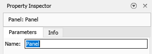
In the Name text box, replace the selected text with
Inputs and Fault Injection.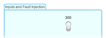
Add Background Image to Panel
You can make your panel look like a real dashboard by adding a background image.
For example, add a background image to the panel you created in Promote Block to Existing Panel:
In the Simulink Toolstrip, on the Panels tab, in the Edit section, click Add Background.
Note
If the panel already has a background image, click Replace Background.
Select an image and click Open.
To exit edit mode, click the canvas.
To delete a background image, select the panel. Then, in the Simulink Toolstrip, on the Panels tab, in the Edit section, click Add Background > Remove Background.
Manage Panel Visibility
When you want more of the canvas to be visible so that you can inspect or edit the model in the canvas, you can collapse or hide your panels.
When you lose track of your panels, you can gather them into the visible model window.
You can also open a panel in a new window.
Collapse Panels
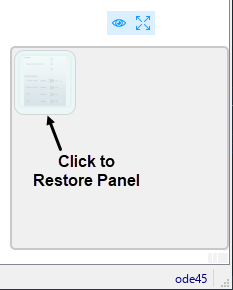
When you want the panel to be readily accessible while you work in the canvas, you can collapse the panel. Collapsed panels remain visible in the model, represented by icons.
For example, collapse and then expand the panel you created in Promote Block to Existing Panel:
To collapse a panel, double-click an empty area in the panel. The panel is replaced by a small blue rectangular icon. The upper left corner of the icon is located where you clicked.
Note
You cannot collapse the panel in edit mode. Double-clicking the panel while in edit mode creates an annotation.

You can reposition the panel when it is collapsed.
To restore the panel, double-click the icon. When you restore the panel, it expands downward and to the right. The top and left edges of the restored panel line up with the top and left edges of the panel in its collapsed state.
Open Panels in New Window
When you want the panel and the model to be in separate windows, you can open a panel in a new window. You can minimize and restore the new window containing the panel separately from the model window. From the panel window, you can run, pause, stop, and step through the simulation.
As an example, open the dashboard panel you created in Promote Block to Existing Panel in a new window. Select the panel. Then, in the Simulink Toolstrip, on the Panels tab, in the Manage section, click Open In New Window.
Alternatively, select the panel and pause on the ellipsis that appears. In the action
menu that expands, click Open in New Window ![]() .
.
Note
If a panel contains Dashboard Scope blocks, you cannot open the panel in a new window during simulation. To open the panel in a new window, stop the simulation.
If a panel has multiple tabs, the panel with all its tabs opens in a new window.
Minimize the model window. When you open a panel in a new window, you can interact with the panel while the model window is minimized. If you work with multiple computer screens, the model and the panel can be on different screens.
You can take these actions using the toolstrip in the panel window.
| Action | Toolstrip Buttons |
|---|---|
| Run simulation. | |
| Pause simulation. | |
| Stop simulation. | |
Step through simulation. To step back, the Enable stepping back parameter
must be set to on. | |
| Set simulation pacing. For more information about simulation pacing, see Simulation Pacing Options. | |
When the panel is unlocked, you can select blocks, jump to the model elements to which they connect, and change their connections. To interact with the gadget that a block represents, for example to push the button a Push Button block represents, you must first click the block to select the block, and then click again to push the button. When the panel is locked, you can interact with the gadget the block represents without selecting the block first. You cannot select the blocks, jump to the connected model elements, or change the connections. | |
| Open panel in model canvas. |
You can also change the simulation stop time by entering a new stop time, specified in seconds, in the Stop Time text box.
As an example, in the panel window you opened, change the simulation stop time to
5 seconds. Then, click Run ![]() . While the simulation is running, modify the position of
one or more of the Slider Switch blocks to simulate a failure in the
system.
. While the simulation is running, modify the position of
one or more of the Slider Switch blocks to simulate a failure in the
system.
To have more time to operate the controls before the simulation ends without changing
the stop time, use simulation pacing. Once the simulation finishes, click Simulation
Pacing ![]() . Then, select Enable pacing to slow down
simulation and move the slider to about
. Then, select Enable pacing to slow down
simulation and move the slider to about 0.8. Run the
simulation again. The stop time is the same, but you have more time to change the position
of the Slider Switch blocks.
To return the panel to the model canvas, click Open in canvas
![]() .
.
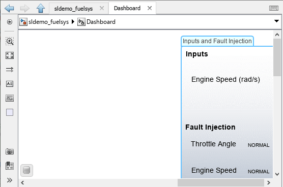
To hide the panel, close the panel window. To unhide the panel, in the Simulink Toolstrip, on the Panels tab, in the Manage section, click Manage Panels. In the Manage Panels menu that appears at the bottom right corner of the model window, click the image of the panel.
Dock Panels
You can dock dashboard panels to the Simulink Editor. You can use the docked panel to monitor signals and control parameters during simulation without covering the model diagram in the canvas.
As an example, dock the dashboard panel you created in Promote Block to Existing Panel.
Select the panel. The panel you created in Promote Block to Existing Panel only has one tab. To dock a panel with multiple tabs, select any tab.
Pause on the ellipsis (…) that appears.
In the action menu that expands, click Dock
 .
.
If the model is open in multiple Simulink windows, when the panel docks in one window, it disappears from the other windows.
By default, panels dock to the right edge of the Simulink Editor. To see where else you can dock the panel, click the canvas. A blue outline appears around the canvas. You can move the docked panel to the left, top, or bottom of the outlined area. To do so, drag the title bar of the docked panel over the side of the outline to which you want to move the docked panel. When a blue area appears, drop the panel.
As an example, move the panel you docked to the left edge of the editor.
Also by default, the docked panel is pinned open.
To minimize and unpin the docked panel, click the down arrow
 and select Minimize. The
docked panel disappears from view, and a tab appears at the right edge of the
Simulink Editor. The tab has the name of the docked panel. To view the docked
panel, click the tab. To minimize the docked panel again, click anywhere in the
canvas.
and select Minimize. The
docked panel disappears from view, and a tab appears at the right edge of the
Simulink Editor. The tab has the name of the docked panel. To view the docked
panel, click the tab. To minimize the docked panel again, click anywhere in the
canvas.To restore and pin open the docked panel, click the docked panel tab. Click the down arrow and select Restore.
To hide the docked panel, close the docked panel window. To unhide the docked panel, in the Simulink Toolstrip, on the Panels tab, in the Manage section, click Manage Panels. In the Manage Panels menu that appears at the bottom right corner of the model window, click the image of the panel.
To select control blocks such as buttons, knobs, sliders, or switches, the control blocks must be inactive. The same is true if you want to connect control blocks, to change the elements to which control blocks connect, or to jump to the element to which a block connects.
You must select an inactive block before you can interact with it. For example, when a Knob block is inactive, clicking the scale only selects the block. To move the handle, you must click a second time. When a Knob block is active, clicking the scale moves the handle. When a block is active, you cannot select or connect the block.
All control blocks are active during simulation. By default, the blocks in a docked
panel are locked in active mode, meaning they are active even when the simulation is not
running. To make the blocks inactive when the simulation is not running, click the Lock
Panel button ![]() .
.
As an example, in the docked panel you created, make the blocks inactive by clicking
the Lock Panel button ![]() . Flip one of the slider switches in the panel. To do so,
you must first select the Slider Switch block. Then, you can click to flip
the switch. Click the Lock Panel button again. Flip the switch back. Since the block is
active, you no longer need to select the Slider Switch block before you can
flip the switch.
. Flip one of the slider switches in the panel. To do so,
you must first select the Slider Switch block. Then, you can click to flip
the switch. Click the Lock Panel button again. Flip the switch back. Since the block is
active, you no longer need to select the Slider Switch block before you can
flip the switch.
To return the docked panel to the canvas, click Open in canvas
![]() . To open the docked panel in a new window, click Open in
new window
. To open the docked panel in a new window, click Open in
new window ![]() .
.
You can dock multiple panels. By default, all panels dock to the right edge of the Simulink Editor, and only one docked panel is displayed. To view a panel that is not displayed, click the corresponding tab below the visible docked panel.
Tip
When you minimize and restore multiple docked panels, multiple docked panels may be visible at once. To view only one, drag the title bar of one docked panel to the center of a second docked panel. When a blue area appears, release the panel. If more than two docked panels are visible at once, drag the title bars of all other docked panels to the center of the same docked panel.
Hide Panels
When you want the panel to disappear from view completely but you do not want to delete it, you can hide the panel.
As an example, hide and then restore the panel you created in Promote Block to Existing Panel:
To hide the panel, select the panel. Then, in the Simulink Toolstrip, on the Panels tab, in the Manage section, select Manage Panels > Hide Panel.
To restore the panel, in the Simulink Toolstrip, on the Panels tab, in the Manage section, click Manage Panels. In the Manage Panels menu that appears at the bottom right corner of the model window, you can toggle the visibility of a panel on or off by clicking its image. Click the panel image to unhide the panel.
Tip
To hide or unhide all panels in the model, click the eye icon above the Manage Panels menu.
Gather Panels into Visible Section of Canvas
Since panels are positioned relative to the canvas and do not scale with zoom actions, panels may move off the edge of the model window in part or in full. To gather all panels in your model into the visible canvas, in the Simulink Toolstrip, on the Panels tab, in the Manage section, click Fit Panels to View.
Note
The Fit Panels to View button does not affect panels that you hide using the Manage Panels menu or the Hide Panel button in the Simulink Toolstrip.
Fit Panels to View also scales all non-collapsed panels up as large as possible within the visible canvas. To fit a single panel to view, you can also press the space bar.
For example, move part of the panel you created in Promote Block to Existing Panel past the edge of the model window.
Then, in the Simulink Toolstrip, on the Panels tab, in the Manage section, click Fit Panels to View. The panel moves and resizes to fit in the model window.

Move Panel in Front of or Behind Overlapping Panels
If two or more panels overlap forming a stack of panels, you can change which one appears at the front and back of the stack.
For example, make a copy of the panel you created in Promote Block to Existing Panel, move one panel over the other, then switch their order in the stack:
If you are in edit mode, exit edit mode.
To create a copy, press Ctrl and drag the panel.
Make the panels overlap by dragging one under or over the other. They do not need to overlap completely.
Select the panel in the front of the stack.
Click Send to Back
 . The panel in the front of the stack moves to the
back of the stack.
. The panel in the front of the stack moves to the
back of the stack.Select the panel at the back of the stack.
Click Bring to Front
 . The panel at the back of the stack moves to the
front of the stack.
. The panel at the back of the stack moves to the
front of the stack.