Design Custom Sliders
This example shows how to use the Horizontal Slider block and the Vertical Slider block to design three sliders that look like controls in real systems:
A light dimmer switch
A medical syringe
A mixing desk slider
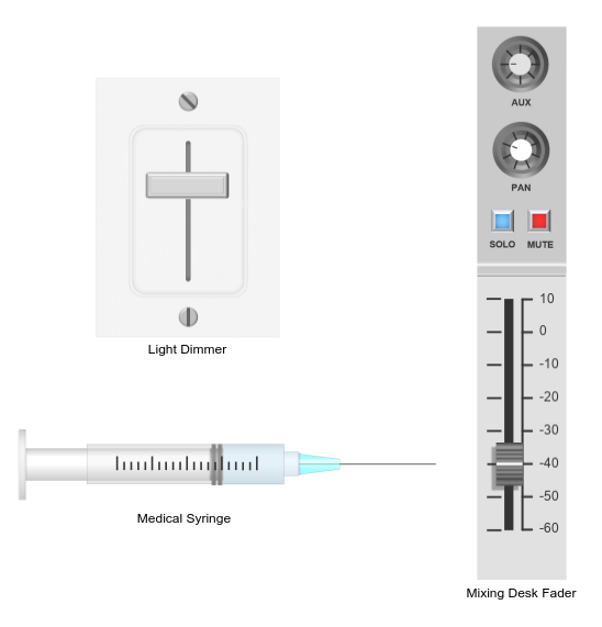
Each slider consists of a stationary component and a movable component. The stationary component is the mounting. The movable component is the handle that you turn to set the value of the parameter that the slider controls.
The blocks in the model use PNG images to define the shapes of these components. You can find all images used to create the sliders in the example directory.
Design Light Dimmer Switch
To design the light dimmer switch, add a Vertical Slider block to the model using the quick insert menu:
To open the quick insert menu, double-click in the canvas.
To search for the customizable Vertical Slider block, type
Vertical Slider.Select the search result with the library path
Simulink/Dashboard/Customizable Blocks.
To modify the design of the Vertical Slider block, enter design mode:
In the model canvas, select the Vertical Slider block.
In the Simulink® Toolstrip, click the Slider tab.
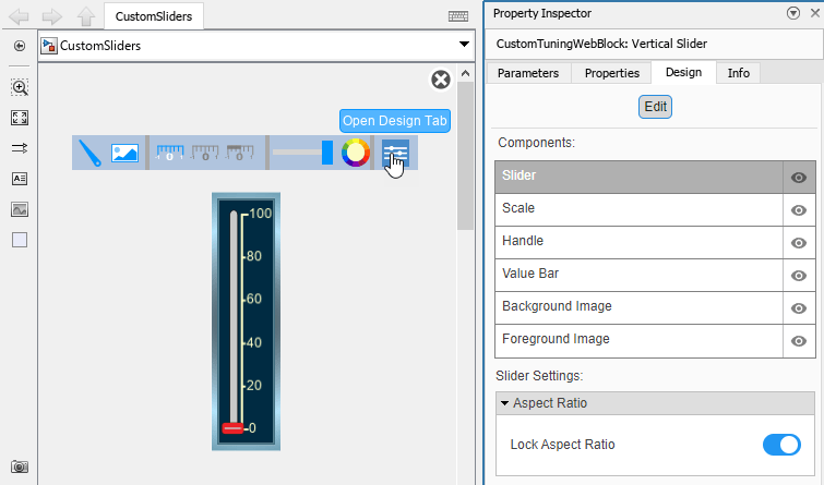
On the Slider tab, click Edit. A toolbar appears above the Vertical Slider block.
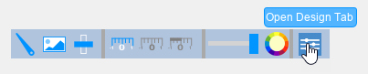
To open the Property Inspector, in the toolbar, click Open Design Tab. In design mode, the Design tab of the Property Inspector is active.
You can design a custom slider using the toolbar or using the Design tab of the Property Inspector. This example uses both.
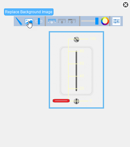
Add the background image for the light dimmer switch:
In the toolbar, click Replace Background Image.
In the
CustomSliderImagesfolder, select thelight-switch-background.pngfile.
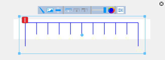
To make the scale easier to see, in the toolbar, click Set Color. Change the scale color to blue.
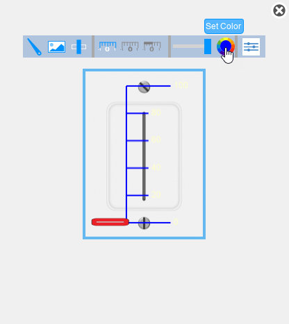
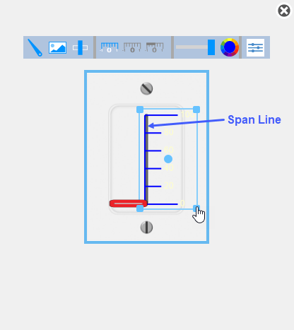
In the canvas, adjust the scale such that the span line exactly covers the slot in the light switch mounting shown on the background image:
To move the scale, click and move the bounding box of the scale.
To resize the scale, click and drag the corners of the bounding box of the scale.
Add the handle image for the light dimmer switch:
In the Property Inspector, on the Design tab, select the Handle component.
In the Select Image section, click the plus button.
In the
CustomSliderImagesfolder, select thelight-switch-handle.pngfile.In the Size section, set the Width and Height to
1.
In the canvas, move the handle to the off position on the light switch mounting shown in the background image. The center of the handle image should be at the bottom of the slot in the light switch mounting.
Hide the scale ticks, span line, and labels:
In the Property Inspector, on the Design tab, select the Scale component.
In the Ticks section, turn off Show Ticks and Show Span Line.
In the Labels section, turn off Show Labels.
Hide the value bar:
On the Design tab, select the Value Bar component.
In the Value Bar section, set the Opacity to
0.
When you finish adjusting the design for the light dimmer switch, to exit design mode, in the Property Inspector, on the Design tab, click Edit.
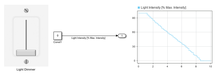
You can use the finished light dimmer switch to control a parameter. In the model, a Constant block represents the light intensity, and the Vertical Slider block controls the value of the constant.
Connect the Vertical Slider block to the Value parameter of the Constant block:
Select the Vertical Slider block.
Click the Connect button that appears above the block.
Select the Constant block named
Const1.In the table that appears below the selected signal, select the
Const1:Value.Click the
Xin the upper right corner of the Simulink window.
To use the light dimmer switch:
Simulate the model. This model uses simulation pacing to slow model execution so you can interact with the model during simulation. For more information about simulation pacing, see Simulation Pacing Options.
Click and drag the Vertical Slider block handle to change the value of the Constant block during simulation.
See the effect on the light intensity in the Dashboard Scope block.
Design Medical Syringe
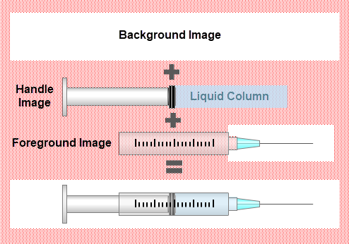
The medical syringe is made with a Horizontal Slider block that has three components:
A background image that is blank and serves only to properly scale the other images
A handle image that shows the handle of the syringe attached to a column of liquid
A foreground image that shows the casing of the syringe with tick marks to indicate the level of liquid inside
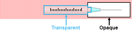
The visual effect that the liquid column vanishes when it passes the tip of the syringe needle is achieved with the opacity of the foreground image.
To show the liquid inside of the syringe, the glass cylinder is transparent in the foreground image.
To hide the part of the handle image liquid column that has moved past the needle tip, the area around the needle tip is opaque in the foreground image.
To design the medical syringe, add a Horizontal Slider block to the model.
If the Property Inspector is not open to the Design tab with the Edit button pressed:
In the model canvas, select the Horizontal Slider block.
In the Simulink Toolstrip, click the Slider tab.
On the Slider tab, click Edit. A toolbar appears above the Horizontal Slider block.
To open the Property Inspector, in the toolbar, click Open Design Tab.
Adding a handle image to a customizable dashboard block changes the aspect ratio of the handle image to match the aspect ratio of the block.
Adding a background image to a customizable dashboard block changes the aspect ratio of the block to match the aspect ratio of the background image.
To prevent the handle image from being distorted, before you add the handle image, you can use a background image to set the aspect ratio of the block to be the same as the aspect ratio of the handle image.
You can prevent the foreground image from being distorted in the same way.
Since the handle and foreground images of the syringe have the same aspect ratio, a background image with that aspect ratio can be used to prevent both from being distorted.
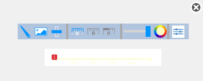
Add the transparent background image for the syringe:
In the Property Inspector, on the Design tab, select the Background Image component.
In the Select Image section, click the plus button.
In the
CustomSliderImagesfolder, select themedical-syringe-background.pngfile.
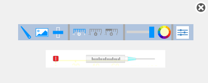
Add the foreground image for the syringe:
On the Design tab, select the Foreground component.
In the Select Image section, click the plus button.
In the
CustomSliderImagesfolder, select themedical-syringe-foreground.pngfile.
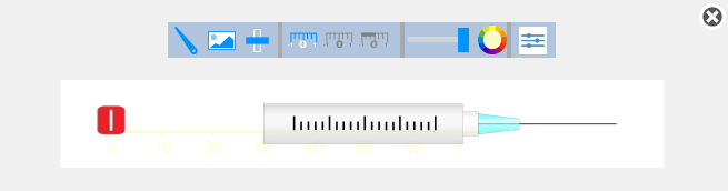
To exit design mode, on the Design tab, click Edit.
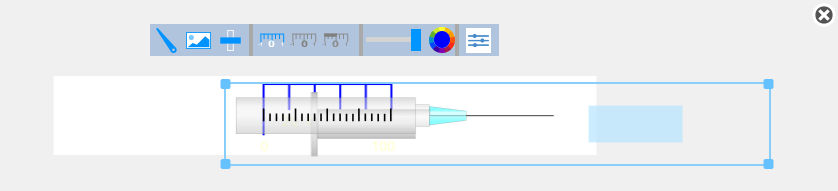
Resize the block in the canvas by dragging one of its corners outwards until the tick marks on the syringe shown in the foreground image are clearly visible.
To continue modifying the design of the Horizontal Slider block, enter design mode. In the Property Inspector, on the Design tab, click Edit.
Make the scale easier to see:
On the Design tab, select the Scale component.
In the Ticks section, change the Color to blue.
At this point, you cannot adjust the size or position the scale in the canvas because the foreground image is on top of the scale.
To make the scale of the Horizontal Slider block match the scale on the foreground image, the handles of the bounding box of the scale need to be outside of the foreground image so that you can adjust the scale with the foreground image visible.
Hide the foreground image:
On the Design tab, click the eye icon of the Foreground Image component. The eye icon now has a slash through it, indicating that the foreground image is hidden.

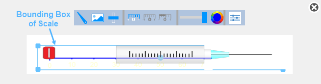
Resize the scale such that you can still grab the handles of the bounding box of the scale when the foreground is visible again:
On the Design tab, click the Scale component.
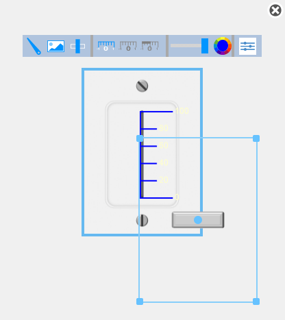
In the canvas, click and drag the corners of the bounding box of the scale such that the top and bottom edges of the bounding box are outside of the white box that is the background image.
To make the foreground image visible again, on the Design tab, click the eye icon of the Foreground Image component.
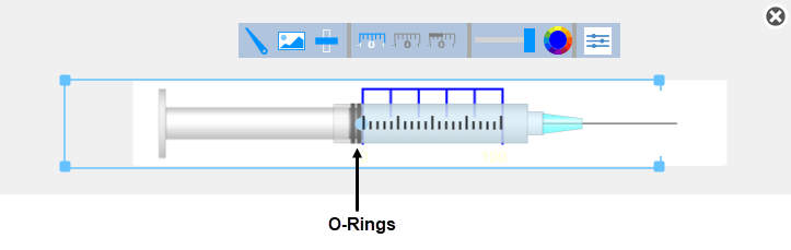
In the canvas, click and drag the corners of the bounding box of the scale such that the left edge of the scale lines up with the leftmost tick mark on the syringe in the foreground image and the right edge lines up with the rightmost tick mark.
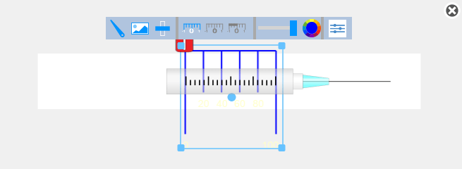
In the canvas, click and drag the corners of the bounding box of the scale such that the top and bottom edges of the bounding box line up with the top and bottom edges of the white box that is the background image.
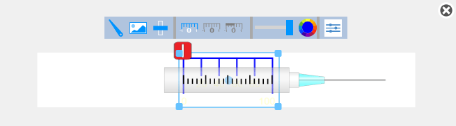
Add the handle image for the syringe:
On the Design tab, select the Handle component.
In the Select Image section, click the plus button.
In the
CustomSliderImagesfolder, select themedical-syringe-handle.pngfile.In the Size section, set the Width and Height to
1.
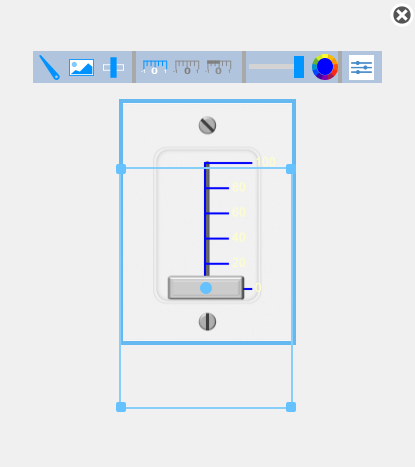
In the canvas, click and drag the edges of the bounding box of the handle image to line up the right edge of the O-rings with the left edge of the scale. Then, line up the top and bottom edges of the handle and foreground images.
Hide the scale ticks, span line, and labels:
In the Property Inspector, on the Design Tab, select the Scale component.
In the Ticks section, turn off Show Ticks and Show Span Line.
In the Labels section, turn off Show Labels.
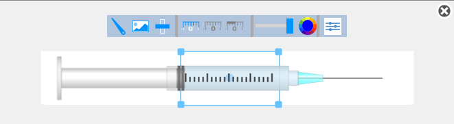
Hide the value bar:
In the Property Inspector, on the Design Tab, select the Value Bar component.
In the Value Bar section, set the Opacity to
0.
When you finish adjusting the design for the syringe, to exit design mode, in the Property Inspector, on the Design tab, click Edit.
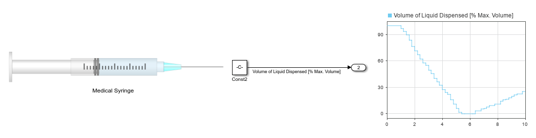
You can use the finished syringe to control a parameter. In the model, a Constant block represents the volume of liquid dispensed, and the Horizontal Slider block controls the value of the constant.
Connect the Horizontal Slider block to the Value parameter of the Constant block:
Select the Vertical Slider block.
Click the Connect button that appears above the block.
Select the Constant block named
Const2.In the table that appears below the selected signal, select
Const2:Value.Click the
Xin the upper right corner of the Simulink window.
To use the syringe:
Simulate the model. This model uses simulation pacing to slow model execution so you can interact with the model during simulation. For more information about simulation pacing, see Simulation Pacing Options.
Click and drag the Horizontal Slider block handle to change the value of the Constant block during simulation.
See the effect on the volume of liquid dispensed in the Dashboard Scope block.
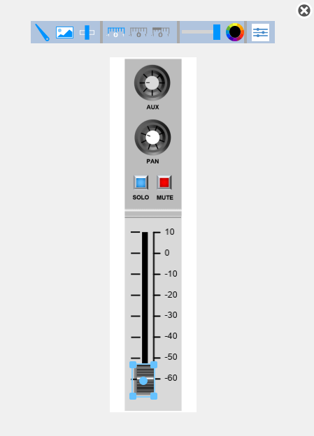
Design Mixing Desk Slider
To design the mixing desk slider, add a Vertical Slider block to the model.
If the Property Inspector is not open to the Design tab with the Edit button pressed:
In the model canvas, select the Vertical Slider block.
In the Simulink Toolstrip, click the Slider tab.
On the Slider tab, click Edit. A toolbar appears above the Vertical Slider block.
To open the Property Inspector, in the toolbar, click Open Design Tab.
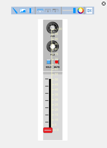
Add the background image for the mixing desk slider:
In the Property Inspector, on the Design tab, select the Background Image component.
In the Select Image section, click the plus button.
In the
CustomSliderImagesfolder, select themixing-desk-slider-background.pngfile.
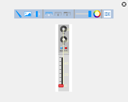
To exit design mode, on the Design tab, click Edit.
Resize the block in the canvas by dragging one of its corners outwards until the text on the background image is large enough to read.
To continue modifying the design of the Horizontal Slider block, enter design mode. In the Property Inspector, on the Design tab, click Edit.
To adjust the scale, you need to be able to see all of the tick marks on the background image. To hide the handle, on the Design tab, click the eye icon of the Handle component. The eye icon now has a slash through it, indicating that the handle is hidden.

Make the scale easier to see:
On the Design tab, select the Scale component.
In the Ticks section, change the Color to black.
In the Label section, change the Color to black.
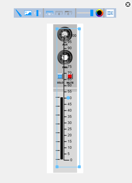
On the Design tab, in the Handle component, in the Range section, set the Minimum to -60 and the Maximum to 10.
In the canvas, click and drag the corners of the bounding box of the scale such that:
The top tick mark of the scale lines up with the top tick mark in the background image.
The bottom tick mark of the scale lines up with the bottom tick mark in the background image.
The left edge of the scale bounding box lines up with the centerline of the slot shown in the background image.
The right edge of the bounding box lines up with the right edge of the mixing desk surface shown in the background image.
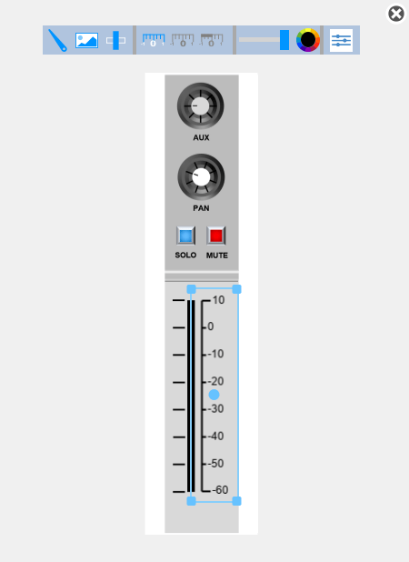
To make the scale easier to read, adjust the height of the tick marks and the offset between the scale labels and the tick marks:
On the Design tab of the Property Inspector, select the Scale component.
To make the tick marks easier to see, in the Ticks section, set the Minor Tick Height to
1.To increase the label offset to make the negative signs in front of scale labels distinguishable from the scale tick marks, in the Labels section, set the Label Offset to
0.15.
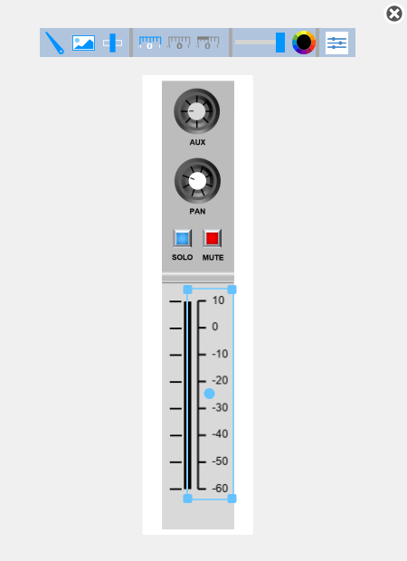
To make the handle visible again, on the Design tab, click the eye icon of the Handle component.
Add the handle image for the mixing desk slider:
On the Design tab, select the Handle component.
In the Select Image section, click the plus button.
In the
CustomSliderImagesfolder, select themixing-desk-slider-handle.pngfile.The handle image is too large to fit on the scale without covering the labels. To make the handle fit, in the Size section, set the Width to
0.245and Height to0.088.
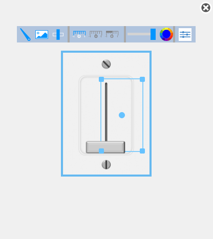
Click and drag the edges of the bounding box to position the handle such that:
The white line shown on the handle image lines up with the
-70tick mark on the scale.The center point of the handle image is on the slot shown in the background image.
Hide the value bar:
In the Property Inspector, on the Design Tab, select the Value Bar component.
In the Value Bar section, set the Opacity to
0.
When you finish adjusting the design for the fader, to exit design mode, in the Property Inspector, on the Design tab, click Edit.
You can use the finished fader to control a parameter. In the model, a Constant block represents the volume of a channel, and the Vertical Slider block controls the value of the constant.
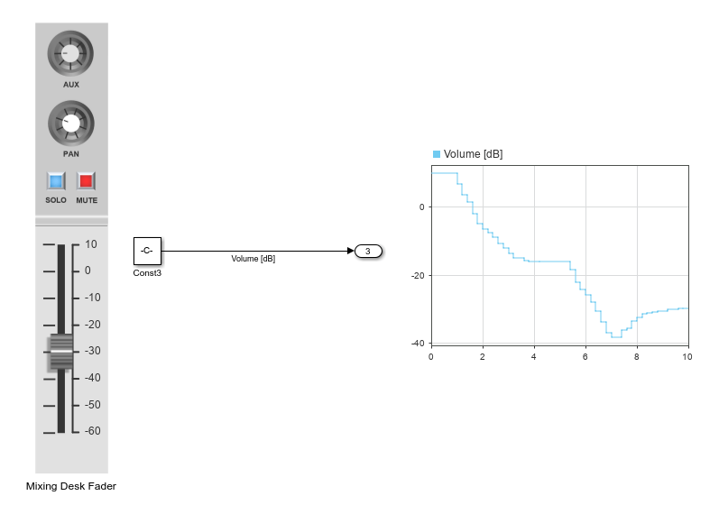
Connect the Vertical Slider block to the Value parameter of the Constant block:
Select the Vertical Slider block.
Click the Connect button that appears above the block.
Select the Constant block named
Const3.In the table that appears below the selected signal, select
Const3:Value.Click the
Xin the upper right corner of the Simulink window.
To use the fader:
Simulate the model. This model uses simulation pacing to slow model execution so you can interact with the model during simulation. For more information about simulation pacing, see Simulation Pacing Options.
Click and drag the Vertical Slider block handle to change the value of the Constant block during simulation.
See the effect on the channel volume in the Dashboard Scope block.