Create Architecture Model and Service Interface
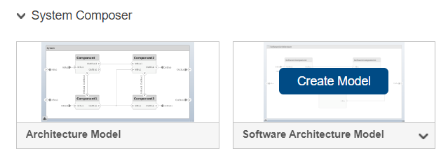
After refactoring the software into a set of components, create a software architecture model to visually represent your service-oriented architecture with components, ports, and connections. Use System Composer™ to start from a Software Architecture Model template. By default, this template allows you to:
Author software architectures composed of software components, ports, and interfaces.
Specify service interfaces on ports to represent component-to-component communication.
Define the execution order of component software functions.
Generate deployable code.
To use the Software Architecture Model template, from the Simulink® Start Page, create a new Software Architecture Model.
To open the software architecture model, run this command.
open("EVPwrCntrllrEMSysInitial.slx");For more information, see Using Software Architecture Model Template (System Composer).
Create Energy Management Component
After you create a new software architecture model, add a software component to represent the energy management functionality.
On the toolstrip, select the Modeling tab, and then drag a software component onto the canvas.

Name the component.
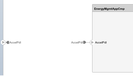
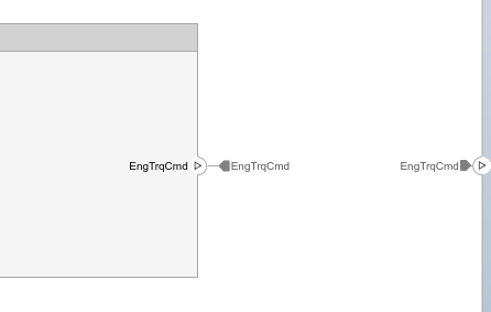
At the root level of the architecture hierarchy, define input and output architecture ports to represent the system interface with external elements. These ports should align with the input and output ports of the monolithic model. Then, add corresponding component ports to the Energy Management component and connect them to enable communication between the system boundary and the internal component.
Create Service Components and Define Interfaces
Create software components and model their communication by defining appropriate interfaces based on the communication type. This example uses two types:
Client-server communication (service interfaces) — Involves client applications that request services or resources from server applications, which then respond to these requests. To model client-server communication, define the functionalities to be provided and requested by services using service interfaces and their function elements.
Sender-receiver communication (data interfaces) — Involves a sender service that transmits data to a receiver service, which then processes the data. To configure a software component for sender-receiver communication, use data interfaces, which are structured interfaces defined by data elements and types for data exchange between software components.
On the toolstrip, select the Modeling tab, and then drag a software component to the canvas for each service component.
Name each component.
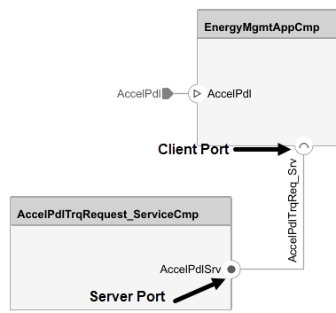
To configure communication between the Vehicle Dynamics and Battery Management System components and the Energy Management component, set up the client and server ports for the client-server interface.
Click the service component boundary to create server ports that represent the functions provided by each service component.
Click the main application component boundary to create the corresponding client port to request these services.
Connect the client and server ports. The connection between these two ports is called a connector.
Use the Interface Editor to define service interfaces, which specify a service functions and arguments. Once defined, System Composer uses these interface definitions to automatically generate model elements, such as ports, connections, and function calls when creating behavior models from the software components in the next section.
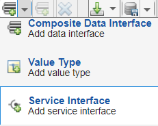
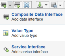
To open the Interface Editor, on the Modeling tab, in the Design section, click the down arrow and select Interface Editor.
Define a data dictionary location for the service interfaces by selecting Save to new dictionary.

Add a new Service Interface for each service.
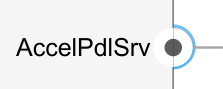
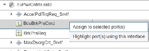
Name the service interface and assign the interface to client and server ports.
Select a client or server port in the diagram.
Right-click the newly created service interface and select Assign to selected port(s).
Tip
The service interface and the port should have distinct names to aid in readability for the two different elements. For this example, for the
AccelPdlTrqRequest_ServiceCmpcomponent, the port name isAccelPdlTrqReq_Srv, and the service interface name isAccelPdlTrqReq_SrvIf.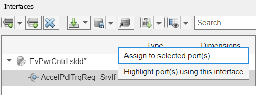
Click the Add element to selected interface icon
 and edit the function
prototype to define the name and arguments of the
function.
and edit the function
prototype to define the name and arguments of the
function.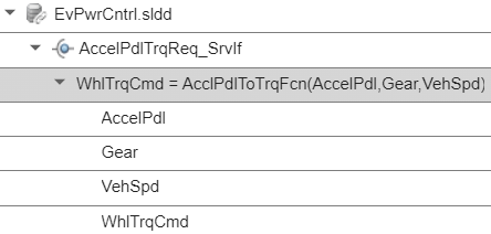
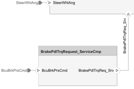
To configure communication between the Brake Pedal Torque Request service component and the Energy Management component, set up the root-level ports for the data interface. In this example, the root-level ports match the input and output ports of the
Brake Pedal to
                                Total Braking Pressure Request
subsystem from the monolithic model.Click the boundary of the service component to create its input and output ports.
Click the boundary of the main application component to create corresponding input ports that will receive data from the output ports of the service component.
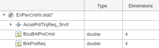
Create value type interfaces in the Interface Editor.
Add a new Value Type for each root-level port in the data dictionary.
Specify the interface name and any associated data attributes. For example, specify the dimensions for the root-level ports in the Brake Pedal Torque Request Service Component to
4.
To assign the value type interfaces to the corresponding root-level ports, first select the root-level port in the diagram.
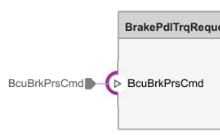
Then, right-click the corresponding interface from the interface editor and select Assign to selected port(s).
Next, define component behaviors in the architecture model to implement the software functionality.
See Also
Topics
- System Composer Concepts (System Composer)
- Compose Architectures Visually (System Composer)
- Author Software Architectures (System Composer)
- Author Service Interfaces Using System Composer (System Composer)