Classic Initialization Mode
Note
Classic initialization mode will be removed in a future release. Use simplified mode instead. For more information about switching to simplified mode, see Convert from Classic to Simplified Initialization Mode.
Initialization mode controls how Simulink® handles the initialization values for conditionally executed subsystems.
Classic mode was the default initialization mode for
Simulink models created in R2013b or before. You can continue to use classic mode
if:
The model does not include any modeling elements affected by simplified mode.
The behavior and requirements of simplified mode do not meet your modeling goals.
The work involved in converting to simplified mode is greater than the benefits of simplified mode.
Set Initialization Mode to Classic
To set classic initialization mode:
Open the Configuration Parameters dialog box. On the Modeling tab and from the Setup section, select Model Settings
 .
.In the search box, enter Underspecified initialization detection.
From the drop-down list, select
Classic.
Classic Initialization Issues and Limitations
Using classic initialization mode can result in one or more of the following issues. You can address these issues by using simplified mode. The description of each issue includes an example of the behavior in classic mode, the behavior when you use simplified mode, and a summary of the changes you must make to use simplified mode.
Identity Transformation Can Change Model Behavior
Conditional subsystems that include identical subsystems can display different initial values before the first execution if both of the following apply:
The model uses classic initialization mode.
One or more of the identical subsystems outputs to an identity transformation block.
Inconsistent Output with Discrete-Time Integrator or S-Function Block
Conditional subsystems that use classic initialization mode and whose output connects to a Discrete-Time Integrator block or S-Function block can produce inconsistent output.
Execution Order Affecting Merge Block Output
The execution order of conditional subsystems that used classic mode initialization, when connected to a Merge block, can affect the output of that Merge block. A change in block execution order can produce unexpected results.
When you rename the Merge block source subsystem blocks, the initial output of the Merge block can change.
When two or more subsystems are feeding different initial output values to a Merge block that does not specify its own initial output value, renaming one of the subsystems can affect the initial output of the Merge block in classic initialization mode.
Simulink Does Not Provide Correct Consistency Check
Simulink does not provide the correct consistency check for settings between two Outport blocks connected through a model reference boundary.
For additional information about the tasks involved to convert a model from classic to simplified mode, see Convert from Classic to Simplified Initialization Mode.
Identity Transformation Can Change Model Behavior
Conditional subsystems that include identical subsystems can display different initial values before the first execution if both of the following apply:
The model uses classic initialization mode.
One or more of the identical subsystems outputs to an identity transformation block.
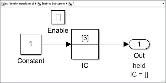
An identity transformation block is a block that does not change the value of its input
signal. Examples of identity transform blocks are a Signal Conversion block or a
Gain block with a value of 1.
In the ex_identity_transform_cl model, subsystems A and B are
identical, but B outputs to a Gain block, which in turn outputs to an
Outport block.

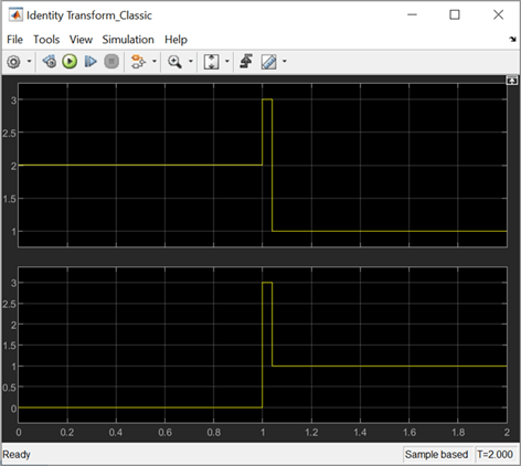
When you simulate the model, the initial value for A (the top
signal in the Scope block) is 2, but the initial value of
B is 0, even though the subsystems are
identical.
Use these steps to use simplified initialization mode and convert
ex_identity_transform_cl to
ex_identity_transform_simpl:
Set Underspecified initialization detection to
Simplified.For the Outport blocks in subsystems A and B, set the Source of initial output value parameter to
Input signal.You can also get the same behavior by setting the Source of initial output value parameter to
Dialogand the Initial output parameter to3.
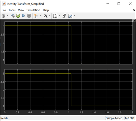
When you simulate the updated model, the connection of an identity transformation does not change the result. The output is consistent in both cases.
Inconsistent Output with Discrete-Time Integrator or S-Function Block
Conditional subsystems that use classic initialization mode and whose output connects to a Discrete-Time Integrator block or S-Function block can produce inconsistent output.
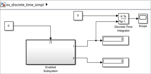
In the ex_discrete_time_cl model, the enabled subsystem
includes two Constant blocks and outputs to a Discrete-Time Integrator block. The
enabled subsystem outputs to two Display blocks.

When you simulate the model, the two display blocks show different values.
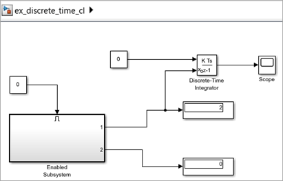
The Constant1 block, which is connected to the Discrete-Time Integrator block, executes, even though the conditional subsystem is disabled. The top Display block shows a value of 2, which is the value of the Constant1 block. The Constant2 block does not execute, so the bottom Display block shows a value of 0.
Use the steps below to use simplified initialization mode and convert
ex_discrete_time_cl to
ex_discrete_time_simpl. The converted model looks the same.
The updated model corrects the inconsistent output issue by using simplified
mode.
Set Underspecified initialization detection to
Simplified.For the Outport blocks Out1 and Out2, set the Source of initial output value parameter to
Input signal. This setting explicitly inherits the initial value, which in this case is 2.You can also get the same behavior by setting the Source of initial output value parameter to
Dialogand the Initial output parameter to2.
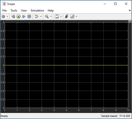
When you simulate the updated model, the Display blocks show the same output. The output value is 2 because both Outport blocks inherit their initial value.
Execution Order Affecting Merge Block Output
The execution order of conditional subsystems that use classic mode initialization, when connected to a Merge block, can affect the output of that Merge block. A change in block execution order can produce unexpected results. The behavior depends on how you set the Output When Disabled parameter.
The ex_basic_merge_sorted_order_1_cl model has two identical enabled
subsystems (Enable A and Enable B) that connect to a Merge block. When you simulate
the model, the red numbers show the sorted execution order of the blocks.


When you simulate the model, the Scope block looks like the following:
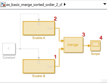
The ex_basic_merge_sorted_order_2_cl model is the same as
ex_basic_merge_sorted_order_1_cl, except that the block
execution order is the reverse of the default execution order. To change the
execution order:
Open the Properties dialog box for the Enable A subsystem and set the Priority parameter to
2.Set the Priority of the Enable B subsystem to
1.
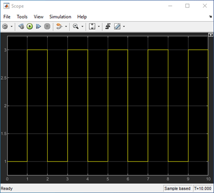
When you simulate the model using the different execution order, the Scope block looks like the following:
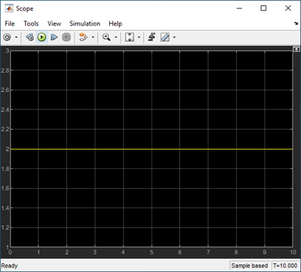
The change in execution order produces different results from identical conditional subsystems.
To update the models and create ex_basic_merge_sorted_order_1_simpl and
ex_basic_merge_sorted_order_2_simpl that use simplified
initialization mode :
Set Underspecified initialization detection to
Simplified.
The Initial Output parameter of the Merge block is an empty matrix,
[], by default. Hence, the initial output value is set to the default
initial value for this data type, which is 0. For information on default initial value, see
Initialize Signal Values. When you simulate each simplified mode model, both
models produce the same results.
Using Output When Disabled Parameter Set to Reset
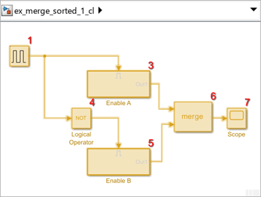
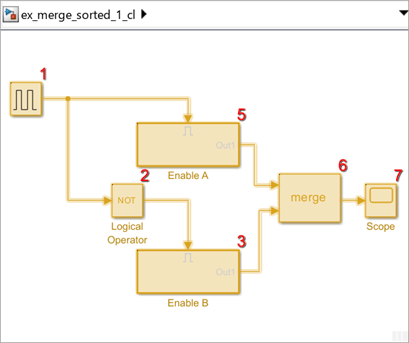
The ex_merge_sorted_1_cl model has two enabled subsystems (Enable A and
Enable B) that connect to a Merge block. When you simulate the model, the red
numbers show the sorted execution order of the blocks.

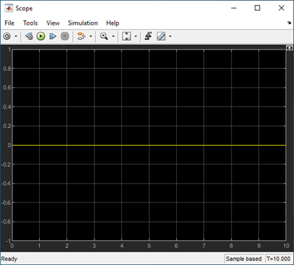
When you simulate the model, the Scope block looks like the following:

The ex_merge_sorted_2_cl model is the same as
ex_merge_sorted_1_cl, except that the block execution
order is the reverse of the default execution order. To change the execution
order:
Open the Properties dialog box for the Enable A subsystem and set the Priority parameter to
2.Set the Priority of the Enable B subsystem to
1.
When you simulate the model using the different execution order, the Scope block looks like:

The change in execution order produces different results from identical conditional subsystems.
To update the models and create ex_merge_sorted_1_simpl and
ex_merge_sorted_2_simpl that use simplified
initialization mode:
Set Underspecified initialization detection to
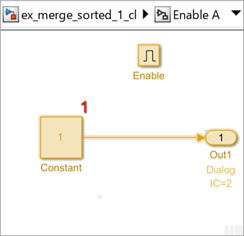
Simplified.For the Outport blocks in Enable A and Enable B, set the Output when disabled parameter to
held. Simplified mode does not supportresetfor output ports of conditional subsystems driving Merge blocks.
When you simulate each simplified mode model, both models produce the same results.
Tunable Parameters
Many block parameters are tunable. A tunable parameter is a parameter whose value can be changed without recompiling the model (see Model Compilation for more information on compiling a model). For example, the gain parameter of the Gain block is tunable. You can alter the block's gain while a simulation is running. If a parameter is not tunable and the simulation is running, the dialog box control that sets the parameter is disabled.
When you change the value of a tunable parameter, the change takes effect at the start of the next time step.
State
Typically the current values of some system, and hence model, outputs are functions of the previous values of temporal variables. Such variables are called states. Computing a model's outputs from a block diagram hence entails saving the value of states at the current time step for use in computing the outputs at a subsequent time step. This task is performed during simulation for models that define states.
Two types of states can occur in a Simulink model: discrete and continuous states. A continuous state changes continuously. Examples of continuous states are the position and speed of a car. A discrete state is an approximation of a continuous state where the state is updated (recomputed) using finite (periodic or aperiodic) intervals. An example of a discrete state would be the position of a car shown on a digital odometer where it is updated every second as opposed to continuously. In the limit, as the discrete state time interval approaches zero, a discrete state becomes equivalent to a continuous state.
Blocks implicitly define a model's states. In particular, a block that needs some or all of its previous outputs to compute its current outputs implicitly defines a set of states that need to be saved between time steps. Such a block is said to have states.
The following is a graphical representation of a block that has states:
Blocks that define continuous states include the following standard Simulink blocks:
The total number of a model's states is the sum of all the states defined by all its blocks. Determining the number of states in a diagram requires parsing the diagram to determine the types of blocks that it contains and then aggregating the number of states defined by each instance of a block type that defines states. This task is performed during the Compilation phase of a simulation.
Simulink Does Not Provide Correct Consistency Check
Simulink does not provide the correct consistency check for settings between two Outport blocks connected through a model reference boundary.
Simulink either throws a false warning or no warning when all of the following conditions are true:
The option Underspecified initialization detection is set to
Classic.The model contains a Model block.
In the referenced model, a root Outport block is driven directly (or indirectly through virtual blocks) by a conditionally executed subsystem. In this scenario, the Outport block corresponding to the conditionally executed subsystem output is a source Outport block.
In the top model, the output port of the Model block that is driven by the source Outport block, in turn, drives a destination Outport block of a conditionally executed subsystem.
If both the source and destination Outport blocks are in the same model, and the settings Initial output and Output when disabled (if applicable) for both Outport blocks differ, Simulink throws an error. However, in the case described above, Simulink either throws a false warning when the two Outport blocks have the same settings or throws no warning or error when they are different.